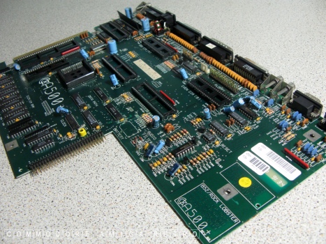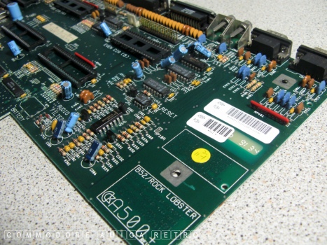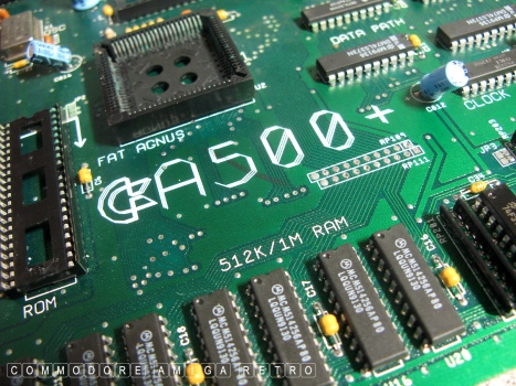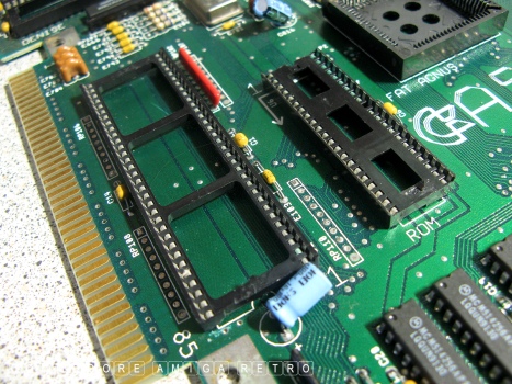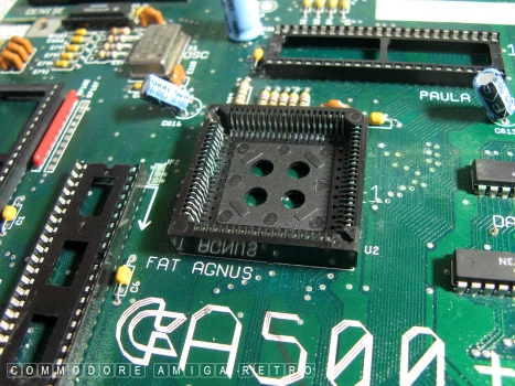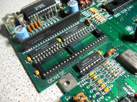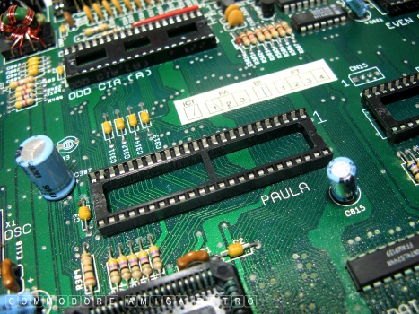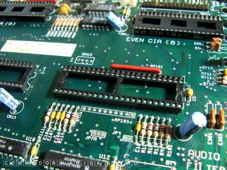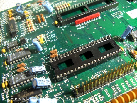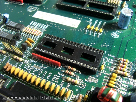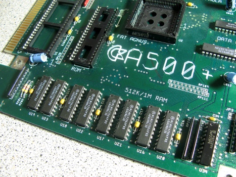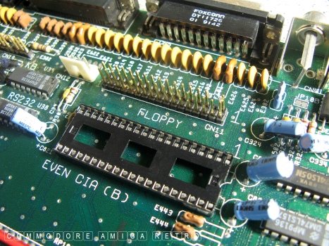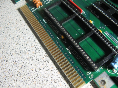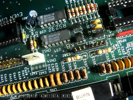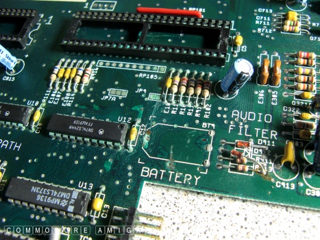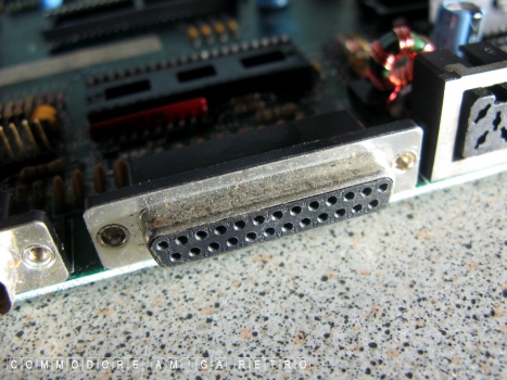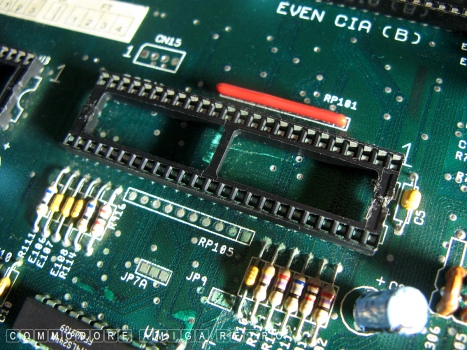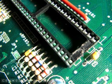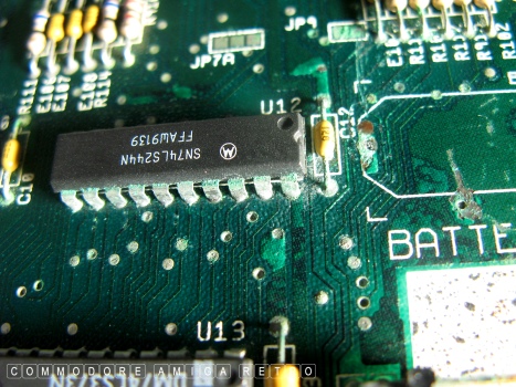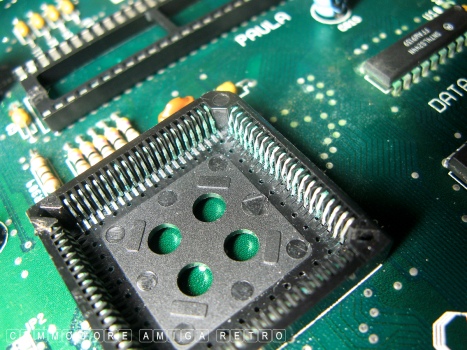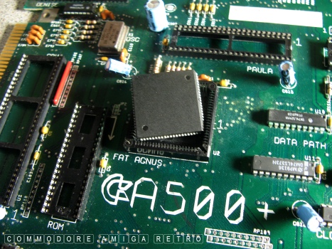
A-500 Plus motherboard less chips.
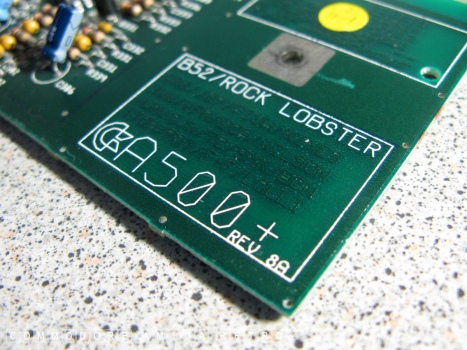
A-500 Plus Revision 8A motherboard.
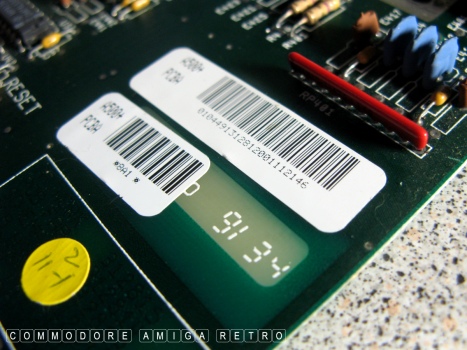
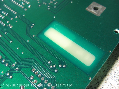
Never noticed the transluscent perspex panel before.
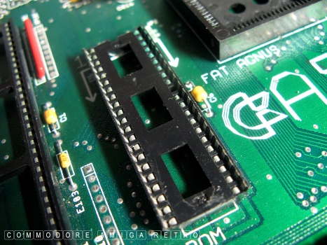
Motorola MC68000P10 CPU and 2.04 ROM sockets.
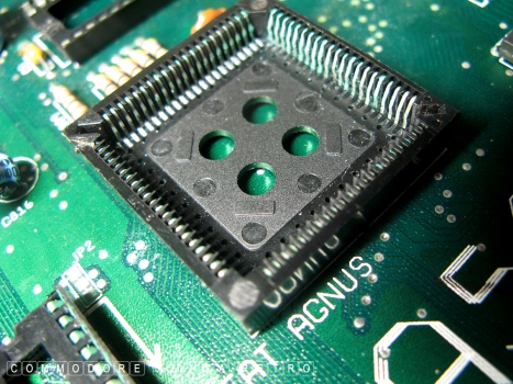
2MB FAT AGNUS socket 8375. Controls 25 system
The 8A board of the PLUS assigns trap door RAM as
The DENISE socket responsible for handling most of
PAULA - Providing native audio 4 channel 8 bit sound
GARY Socket ref 5719 gate array chip plus control
First of two CIA chip sockets labelled EVEN and ODD
Second of two CIA chip sockets labelled EVEN and ODD
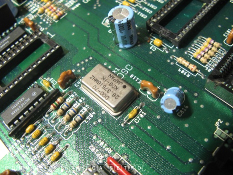
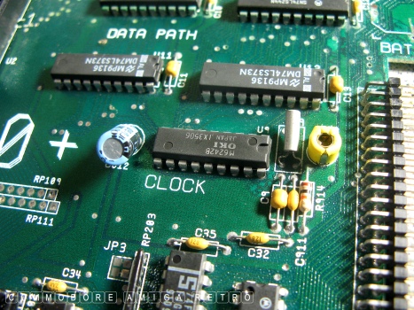
28.37516 MHz Crystal Oscillator PAL
The A-500 Plus imports the 512K A501 card
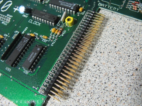
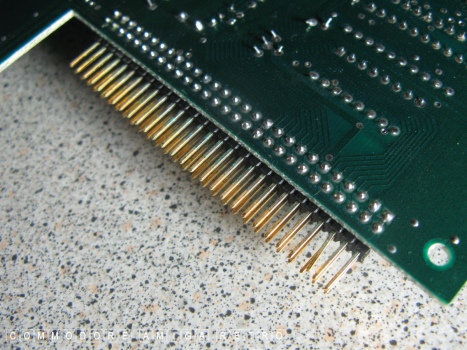
56 pin trapdoor connector.
Floppy disk drive 34-way, 2-row header plug.
86 pin Zorro expansion port connector.
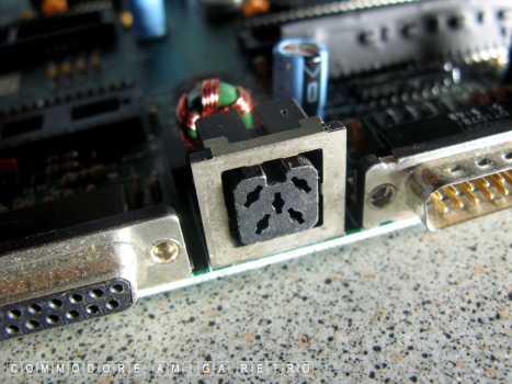
Floppy power and keyboard connector. Note
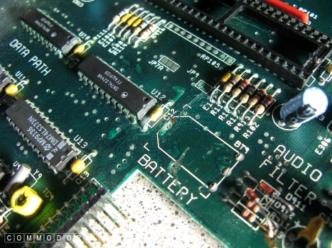
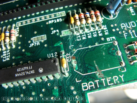
The barrel battery location for the RTC.
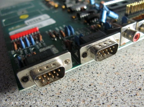
9-pin D-Sub mouse [ left ] joystick [ right ] port.
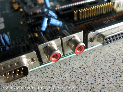
Left and right audio jacks.
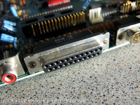
23 pin D-Sub female disk drive port.
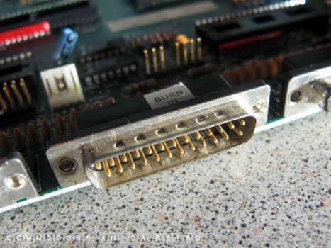
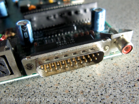
23 pin male serial port.
23 pin D-sub Parallel port female.
Power supply from external PSU.
23 Pin RGB video port male plus composite
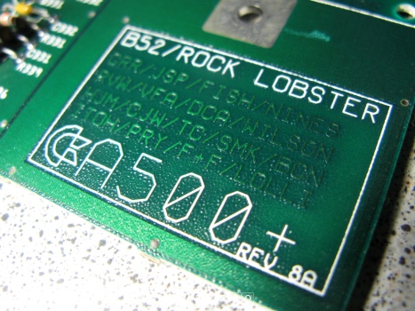
B52 refers to the band and the music track
That transluscent panel in the board that
The AGNUS often has holes in the board to allow
Corrosive residue local to removed battery.
Green corrosion to socket feet for GARY chip.
Note that previous owner removed the chip using
GARY chip socket with green corrosion.
The components around the battery show signs
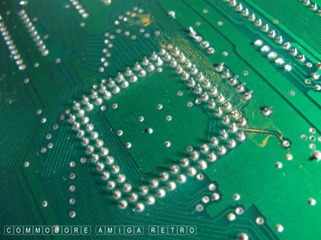
AGNUS socket pins showing green corrosion.
Pins eventually snap off and cause system failure.
There is no obvious leakage on the board up to
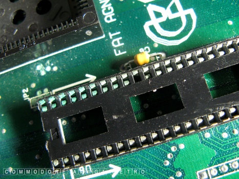
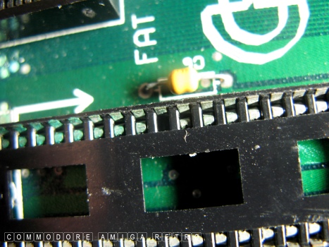
The left of the ROM chip is green to socket feet.
One socket receiver has broken off sadly.
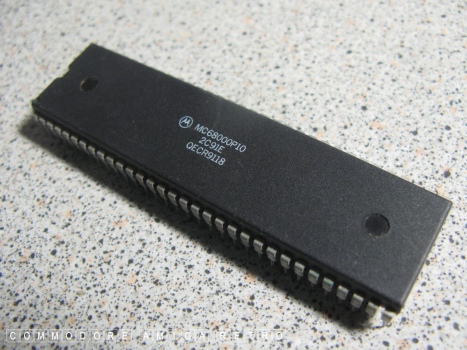
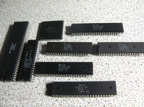
Main processor chip.
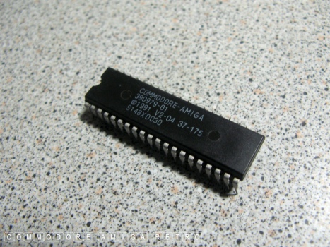
The 2.04 ROM.
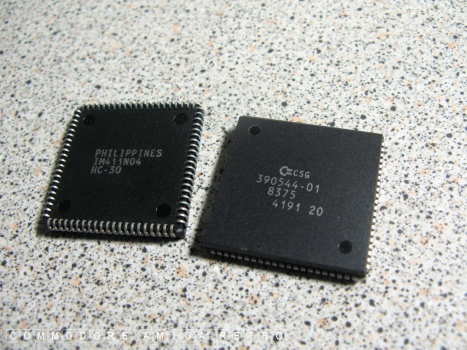
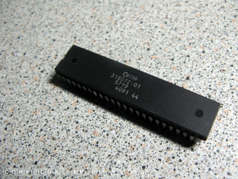
ECS 2MB FAT AGNUS 8375.
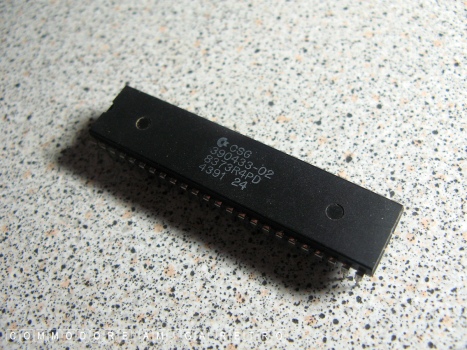
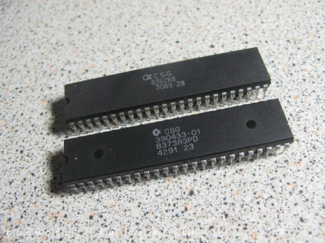
Super DENISE ECS 8373R4PD.
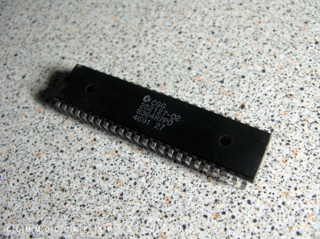
PAULA 8364R7PD.
GARY 5719.
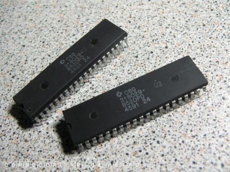
2 No identical CIA chips 8520PD.
A500 OCS DENISE and a Rev 3 Super Denise.
The Amiga 500 Plus full set of main chips.
The FAT AGNUS on this board had no markings
Only way to see if she will work is to
Further, this board needs a new ROM and
ScuzzBlog: Diaries February 2024
Entry 2nd February 2024: Post 1: Amiga 500 Plus - Motherboard chips and battery damage.
Amiga 500 Plus - Motherboard chips and battery damage.
I often see comments on various blogs regarding battery damage to
an A500 Plus as being contained to the discharge around the battery
itself. Today I show just how far the damage actually spreads.

I include also a descriptive of the Amiga 500 Plus custom chips
and various connectors.

The motherboard I show here is 'shot'. I sense it arrived this way
and already had the battery removed. There are a few scratches
around the battery area that look a little hostile. Not something
I would have done. Interestingly with a new ROM socket and perhaps
a fresh AGNUS socket this thing may just spring back into life. A
check on track continuity would be essential, but on the face of
it they still look OK. I have suffered a lot worse and kept the
board alive.
Amiga 500 Plus - Motherboard chips and battery damage.
DMA channels and addressing CHIP RAM. The AGNUS
also contains an integrated Copper (co-processor).
Moves blocks of memory asynchronously leaving the
processor free to undertake other operations.
CHIP RAM unlike the A500.
the graphics tasks. The Amiga 500 Plus has the ECS
Super Denise 8373R4PD and in addition to the 4096
colours in HAM-6 mode supports also extra half brite.
plus floppy drive controller. Ref 8364R7PD.
logic for certain busses.
Both identical and responsible for various I/O functions
such as the serial, parallel, joystick & mouse ports.
Both identical and responsible for various I/O functions
such as the serial, parallel, joystick & mouse ports.
RAM with what was 512K on the motherboard
to give a combined 1MB of CHIP RAM.
All odd numbered pins are connected to ground
Pin 3 missing on all machines.
that pin to keyboard is always missing.
Cause of much damage on these machines.
A-500 Plus only. On the A500 computers the
battery RTC was in a metal shielded A501 RAM
expansion connected to the trapdoor connector.
black and white only jack. Note that RF
and colour composite provided by external
A520 modulator connected to RGB port.
called Rock Lobster. Names of all those
involved in the development of this computer
at Commodore. Note the 8A revision number.
appears to show label details from other side.
easy removal of the chip. Not on this board.
Spread of battery corrosion and damage.
Note the green discolouration on the trapdoor pins.
a screwdriver instead of a chip remover and in doing
so scratched and damaged the motherboard.
of corrosion. They will continue to corrode
long after the battery is removed.
the ROM chip and yet the socket has corroded.
rendering the socket unusable.
A-500 Plus Chips
on the face of the chip.
check the continuity of tracks.
AGNUS socket and that is beyond my abilities.
What I did do in the day was remove and replace
the motherboard. Was the simplest solution. I
do keep all my chips as spares.

If you can only see this CONTENT window
then click the image above for the full site
Last updated 2nd February 2024
Chandraise Kingdom
![]()
Keep the Faith
scuzzscink 2024

