
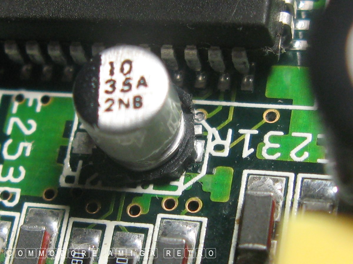
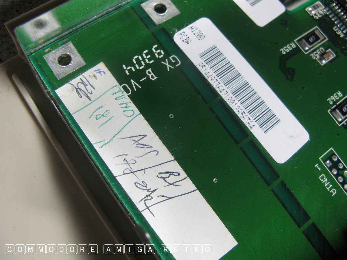
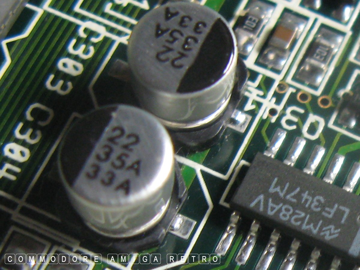
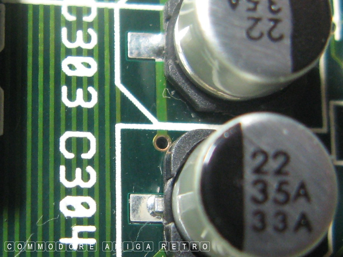
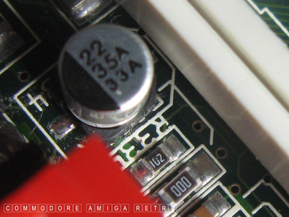
My guess it slipped during production.
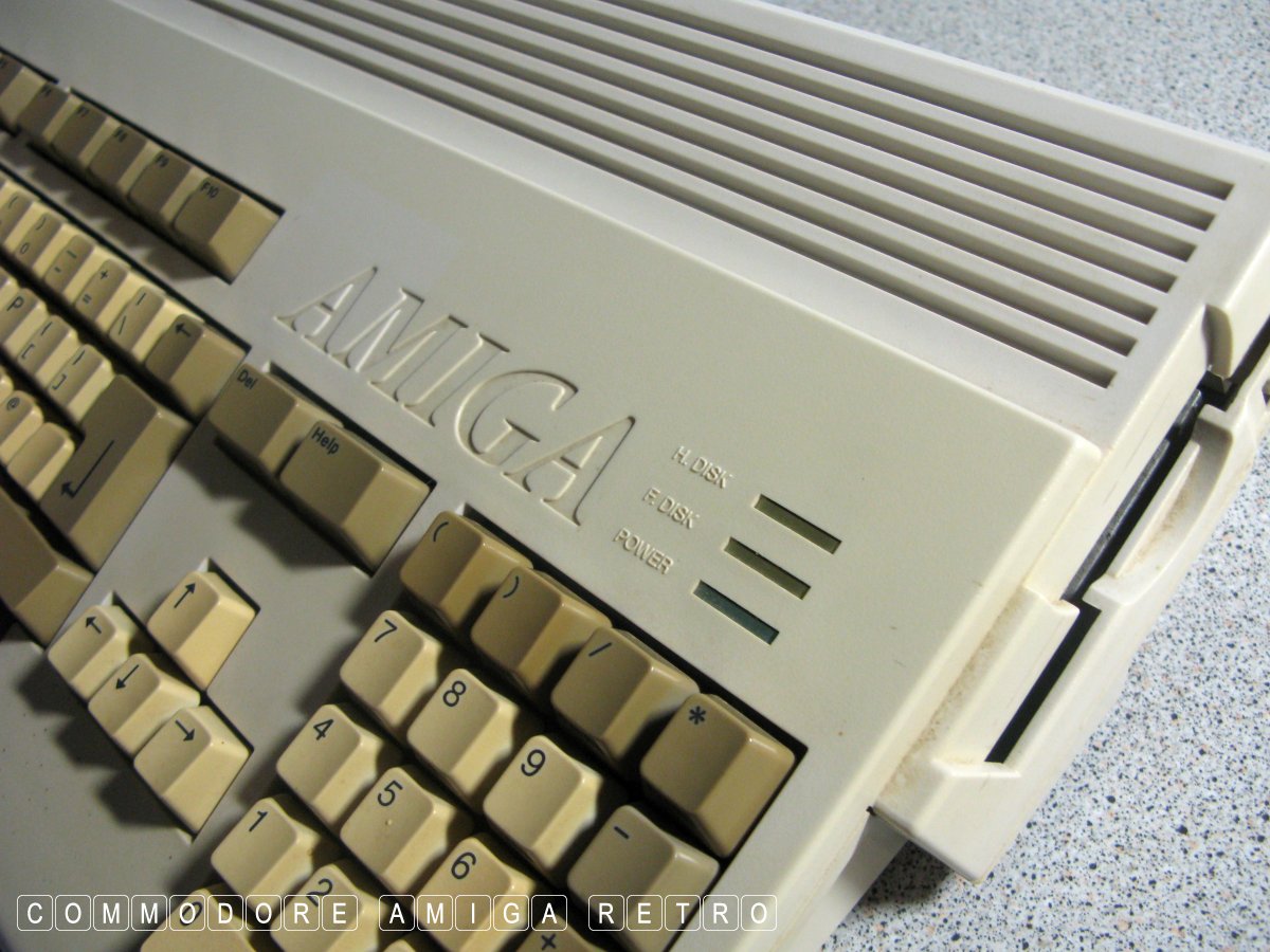
My rare Amiga with no name.
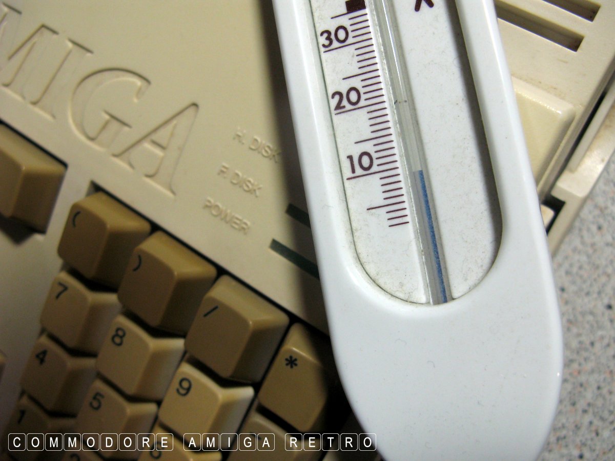
Just nine degrees today ... brrr brrr.
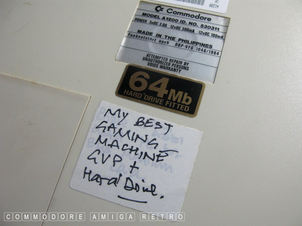
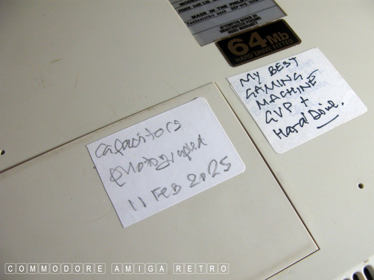
Classic Philippines Amiga 1200.
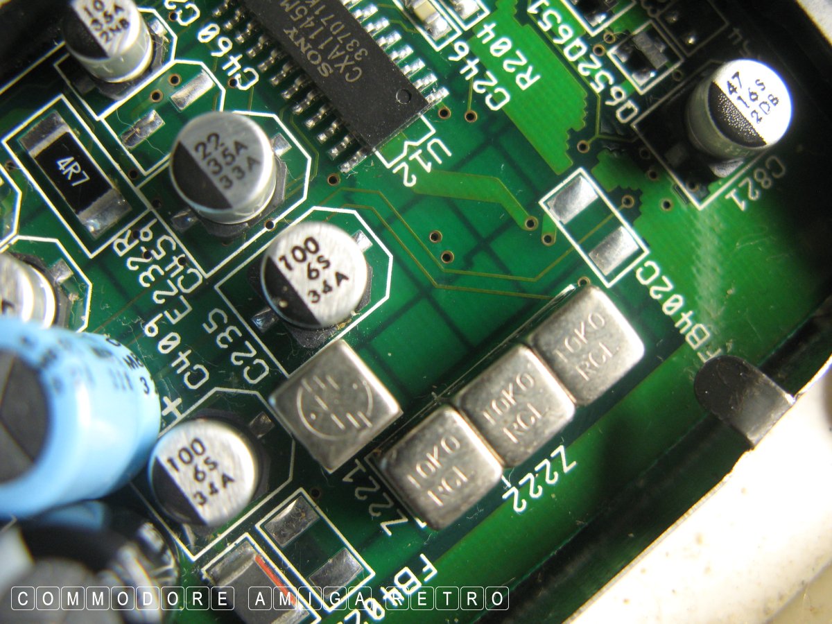
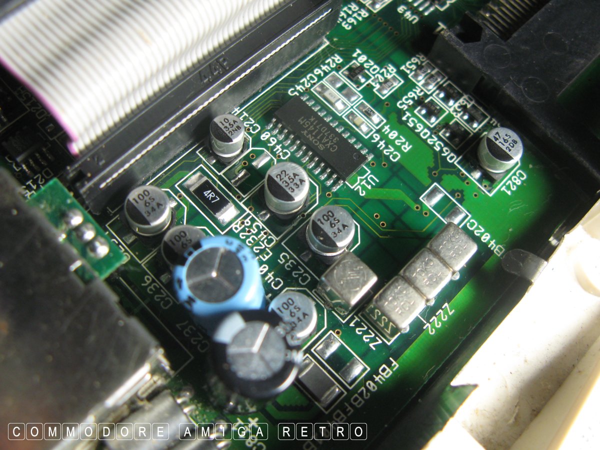
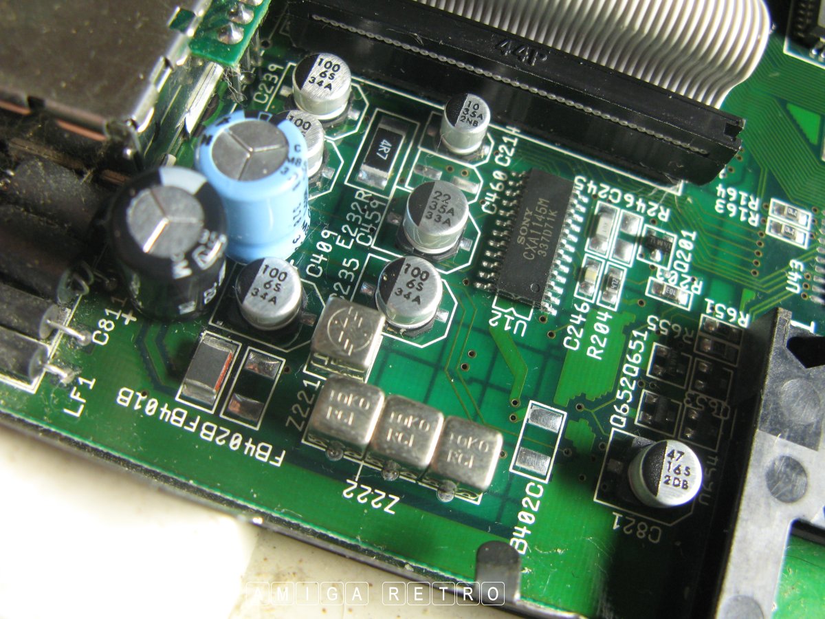
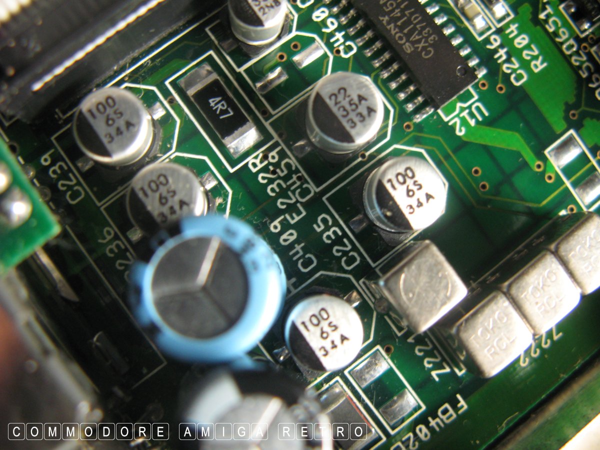
Only the best capacitors will do.
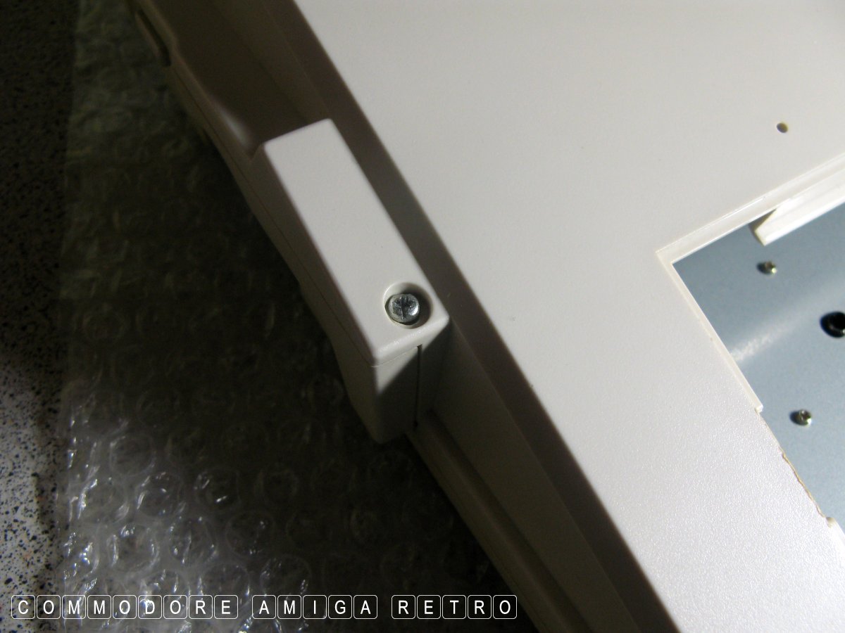
OK first up lets open the trapdoor on the base.
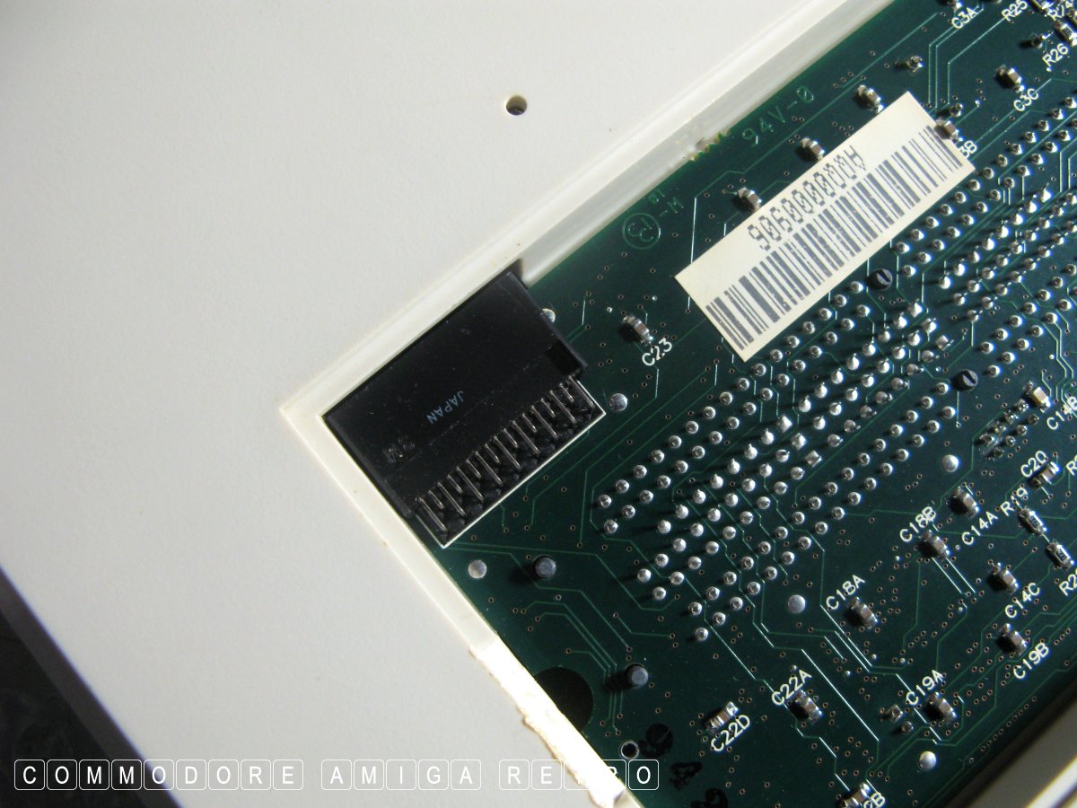
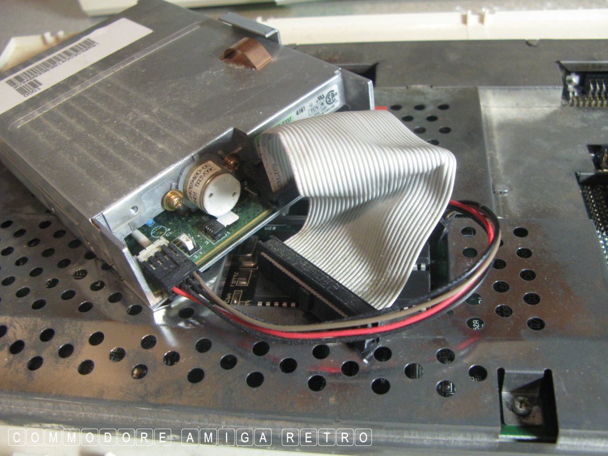
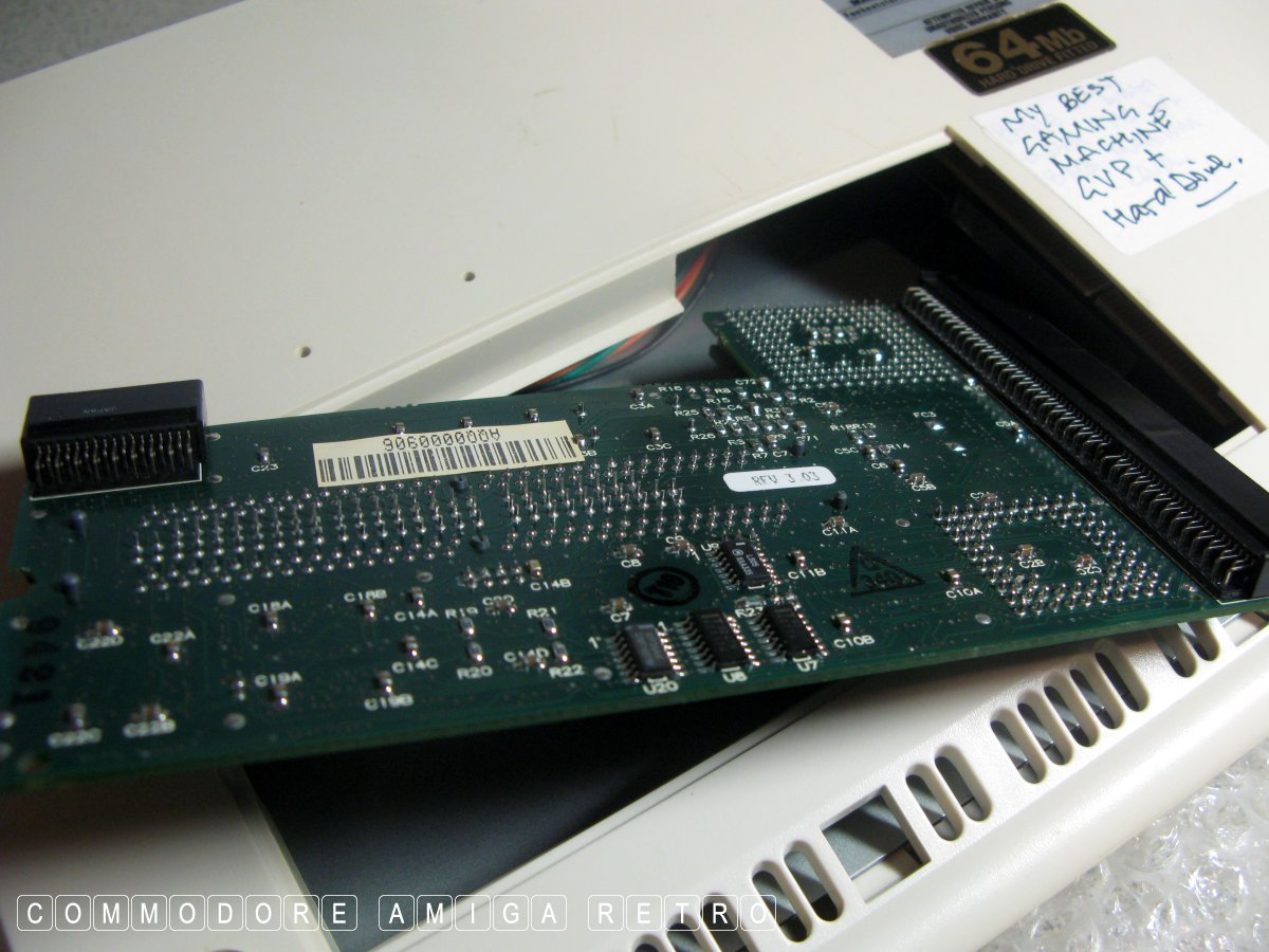
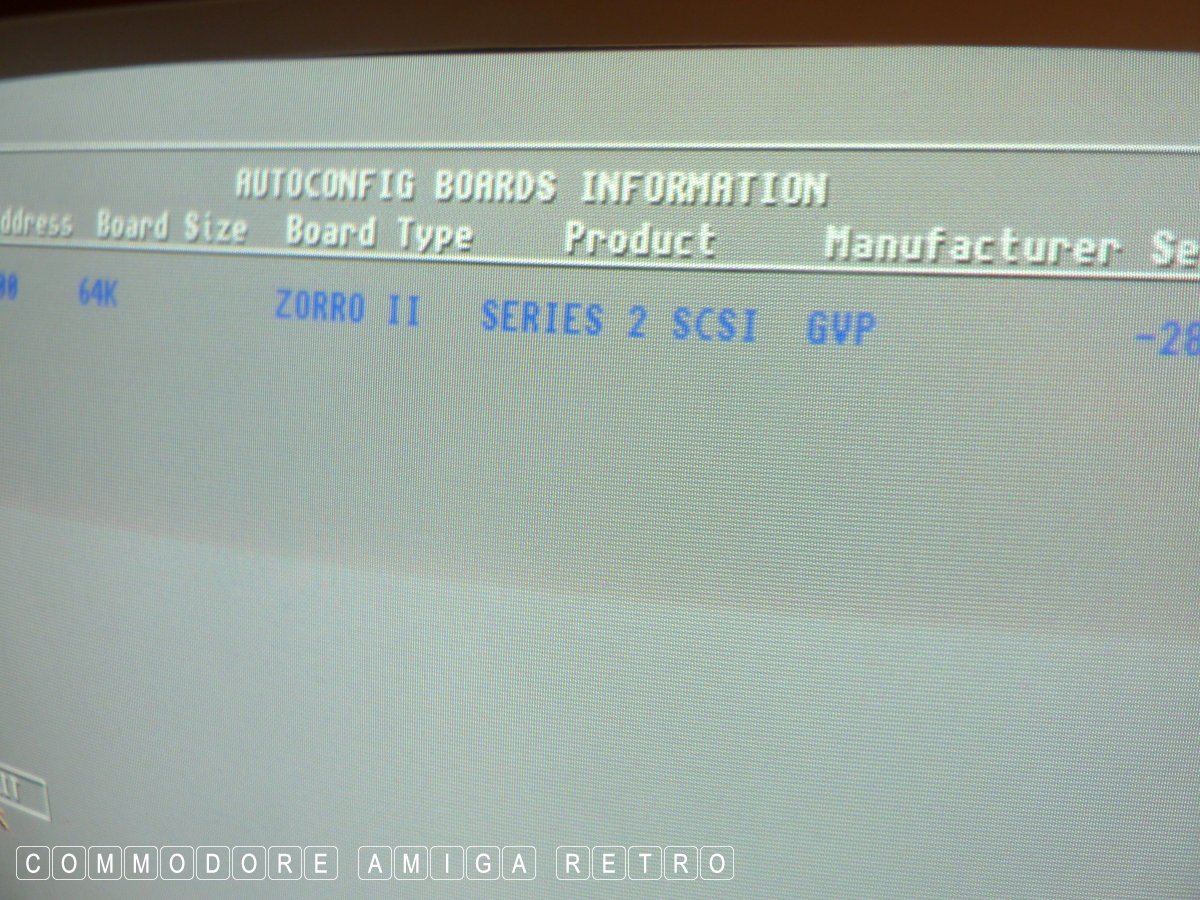
A GVP JAWS II with the SCSI connector.
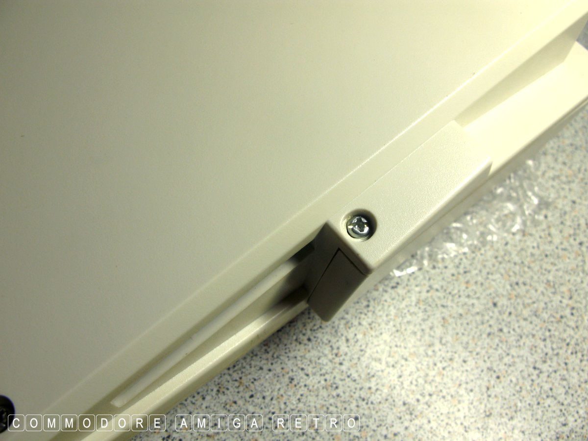
Always check the rubber feet to see if
OK screw one middle left and maybe longer
Screw two middle right. Same applies as
There are now three smaller type self tappers
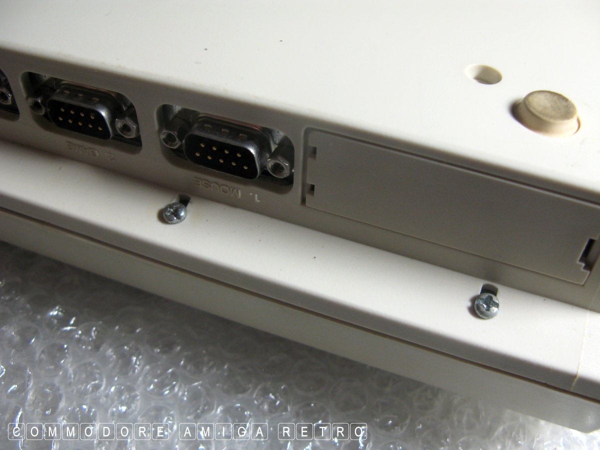
These two screws hold the floppy drive and are
Often there is no need to remove the floppy drive
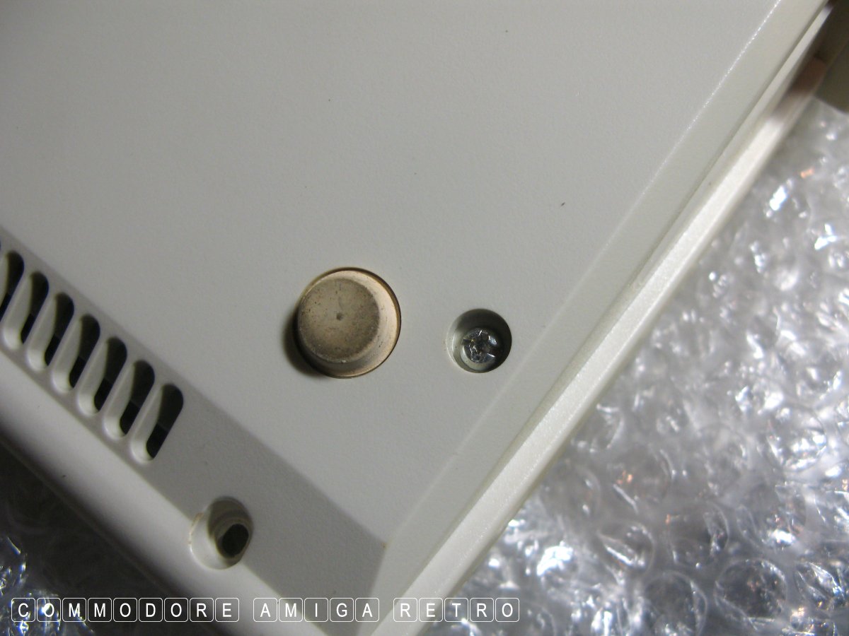
This screw holds down the bottom corner shielding
With all screws removed simply lift the top
There is a cable to the LED on the case that
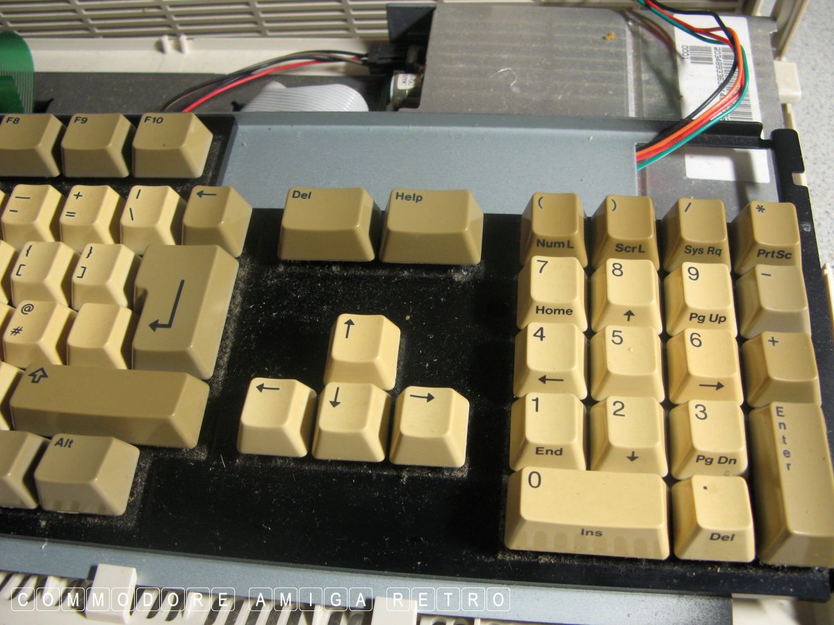
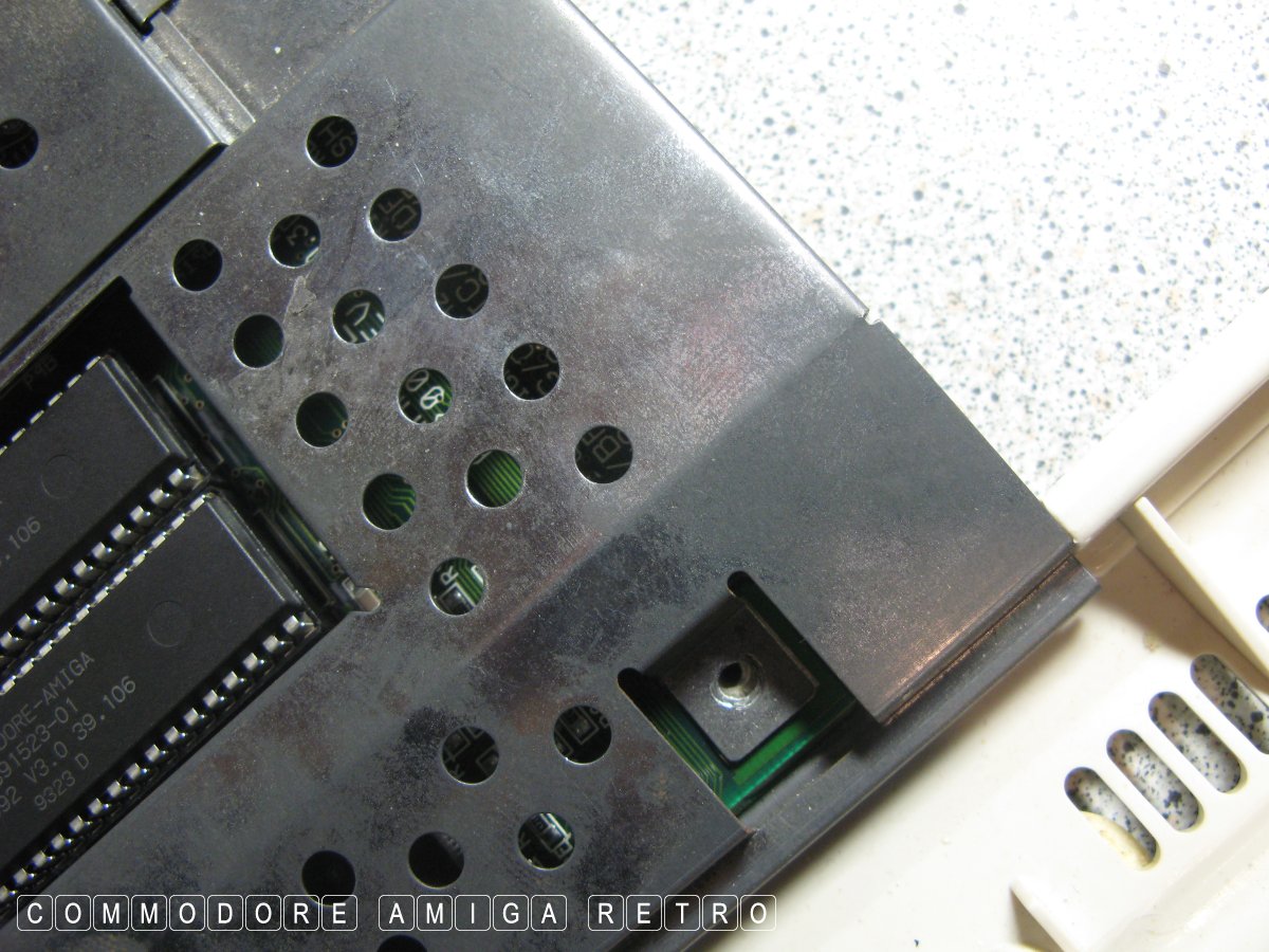
Always worth cleaning out the dust from
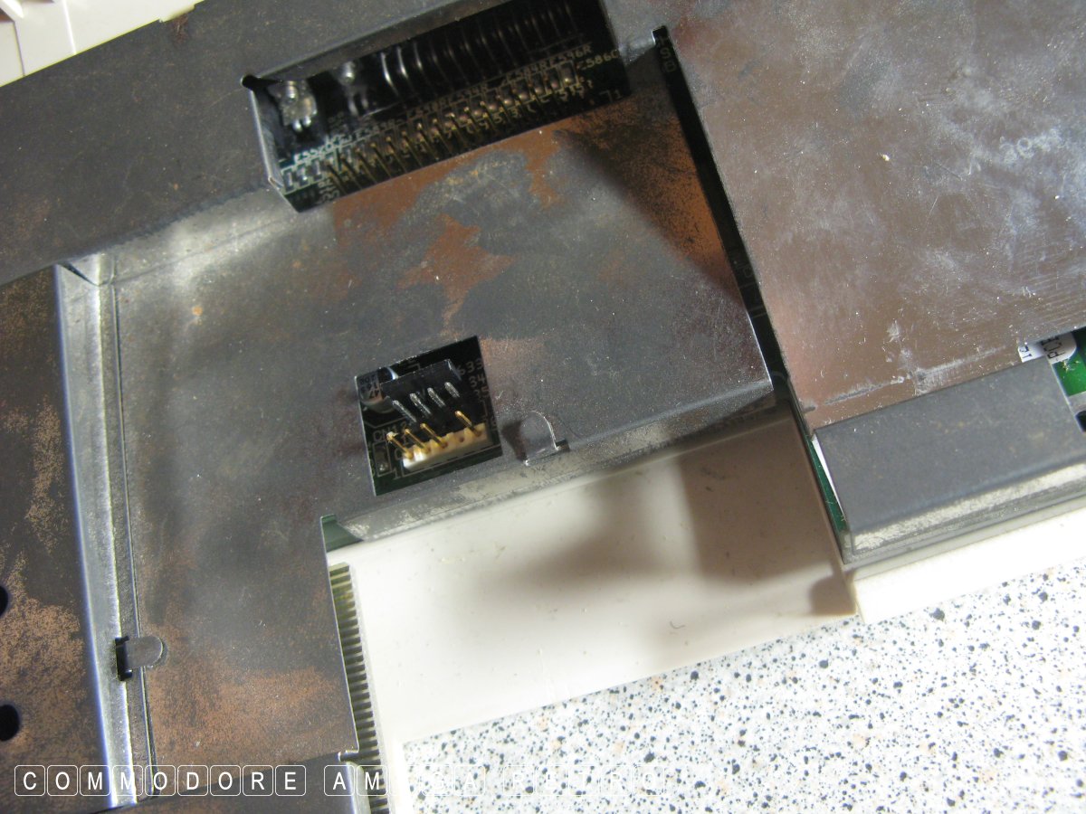
Note the little slot for the bottom edge of
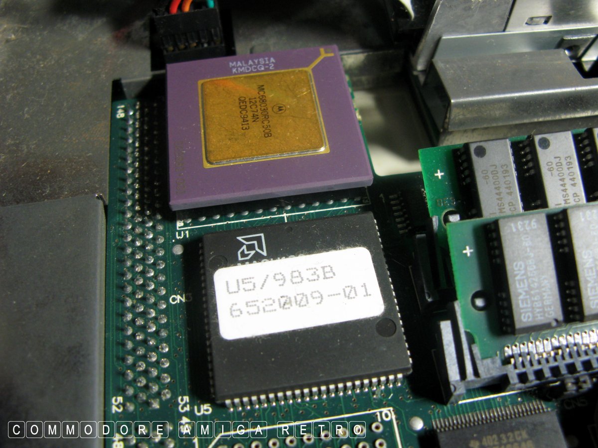
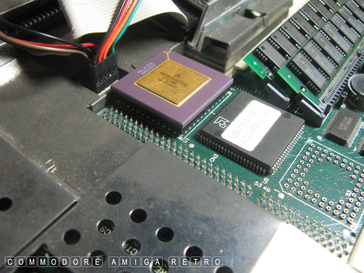
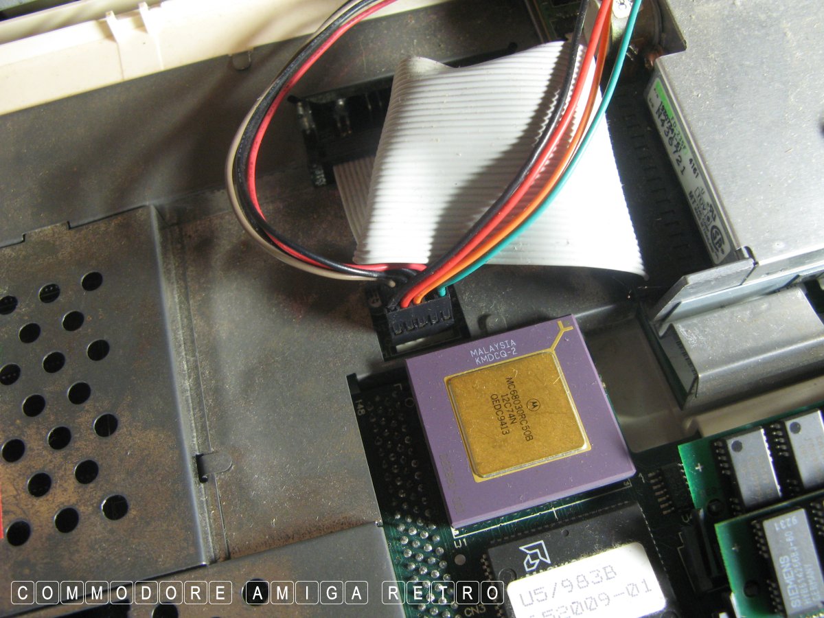
This is the GVP accelerator which I always remove.
Always remove from below and avoid trying to
Amazingly the clock still maintains the correct time.
A gold and purple chip generally means acceleration.
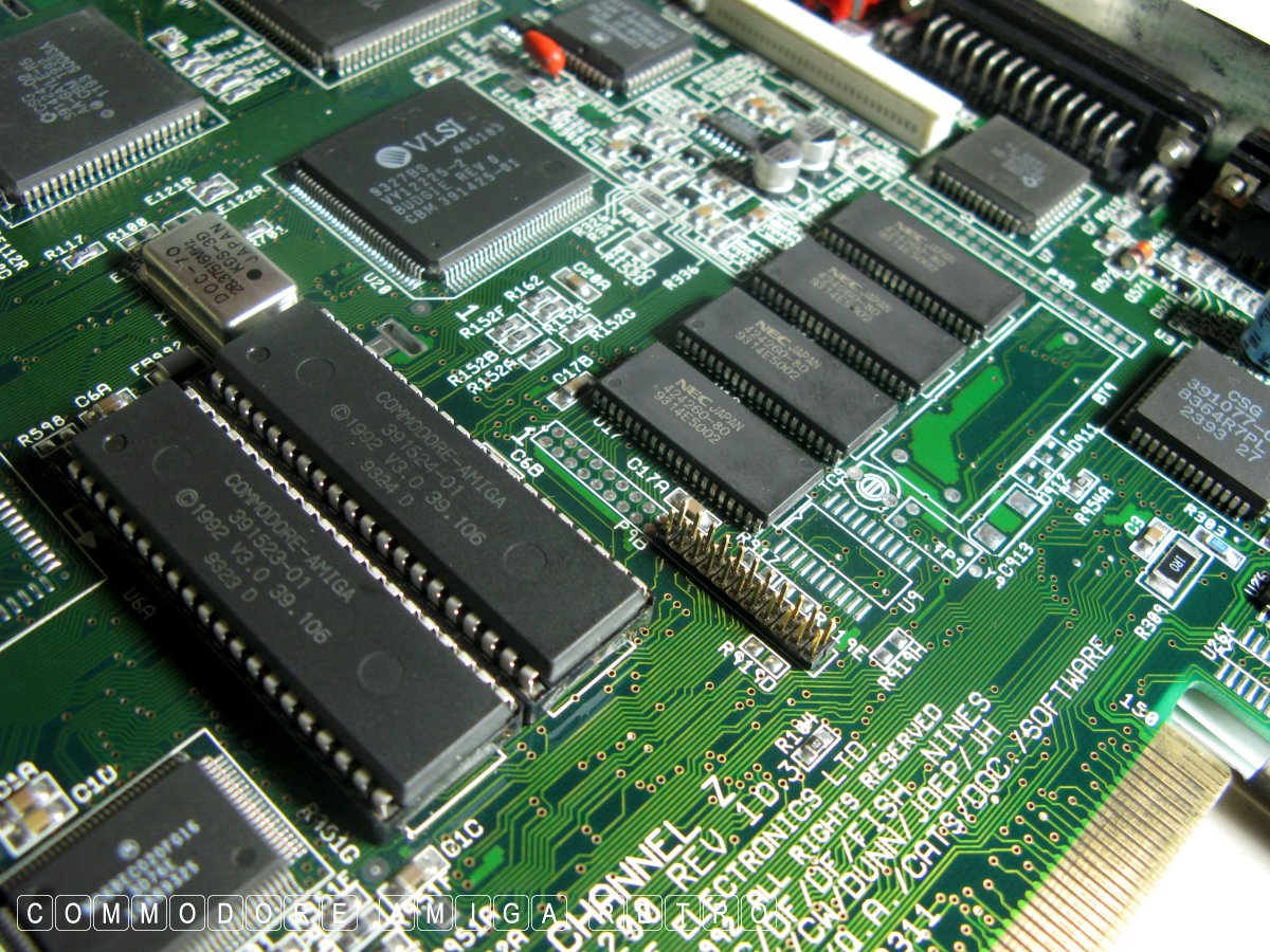
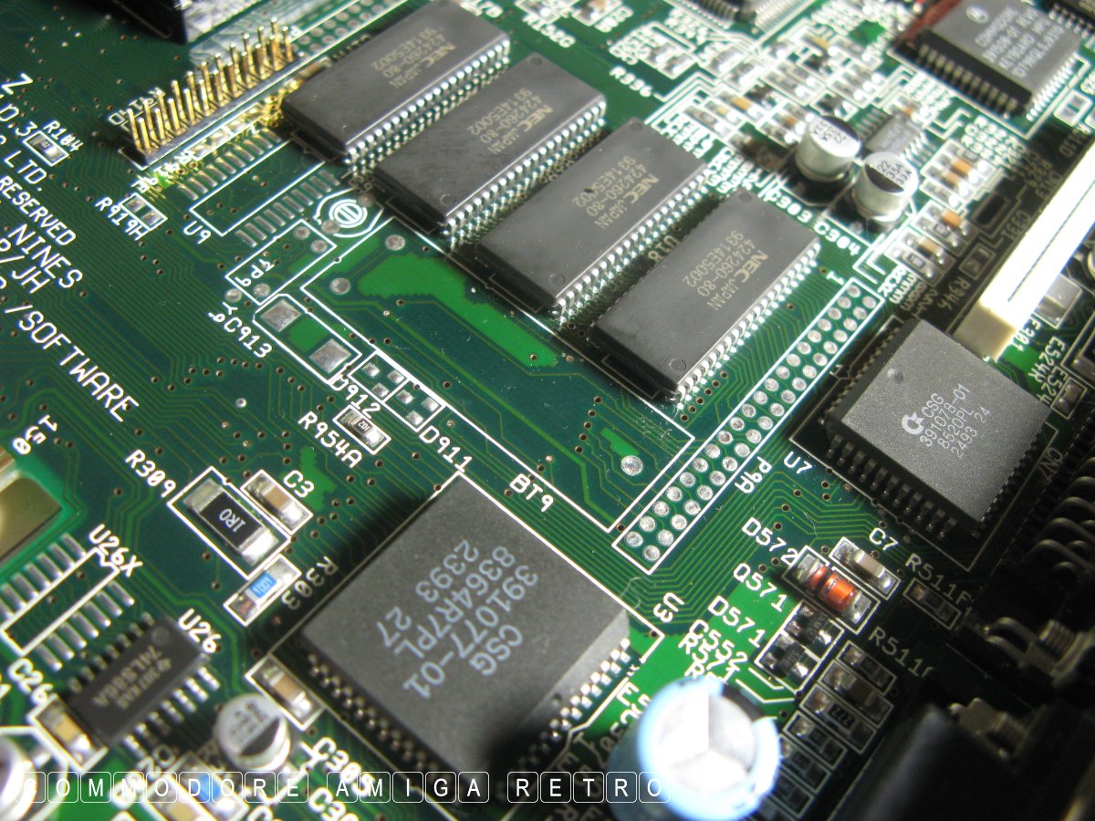
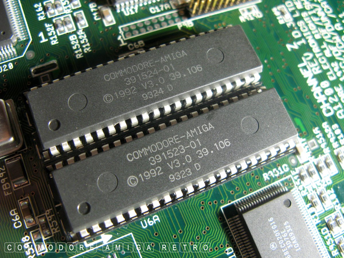
These are the ROM chips and define the kick
Note the spare socket slots to the left. The
There are only two screws holding the shielding down
This is the second which we unscrewed from
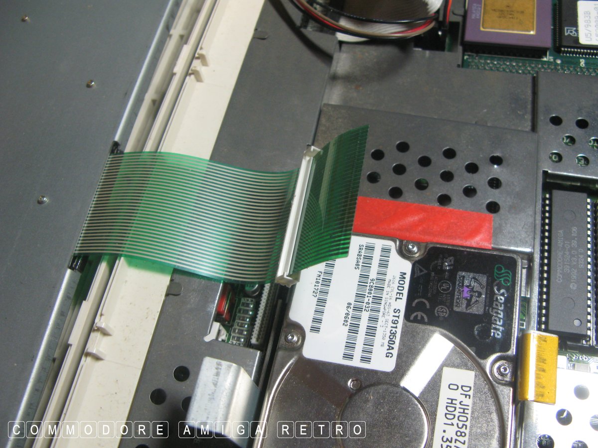
The Amiga 1200 generally used a 2.5" laptop
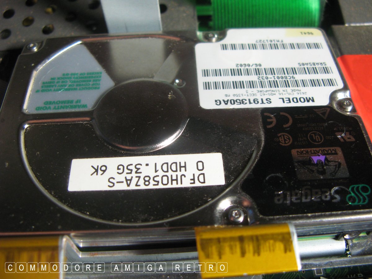
A Seagate 1.35GB hard drive and one of my
I like to isolate the drive from the shielding
I need to get that accelerator out of the way.
Just above the accelerator are the two connectors
It is worth writing down the wire colours
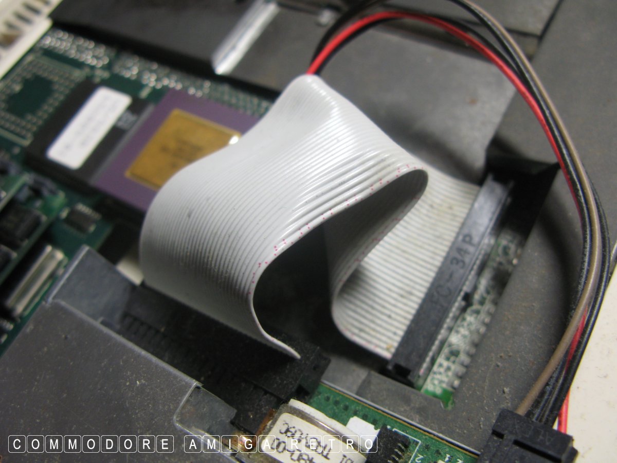
Never simply pull out the ribbon cable. Use
Next pull out those power cables.
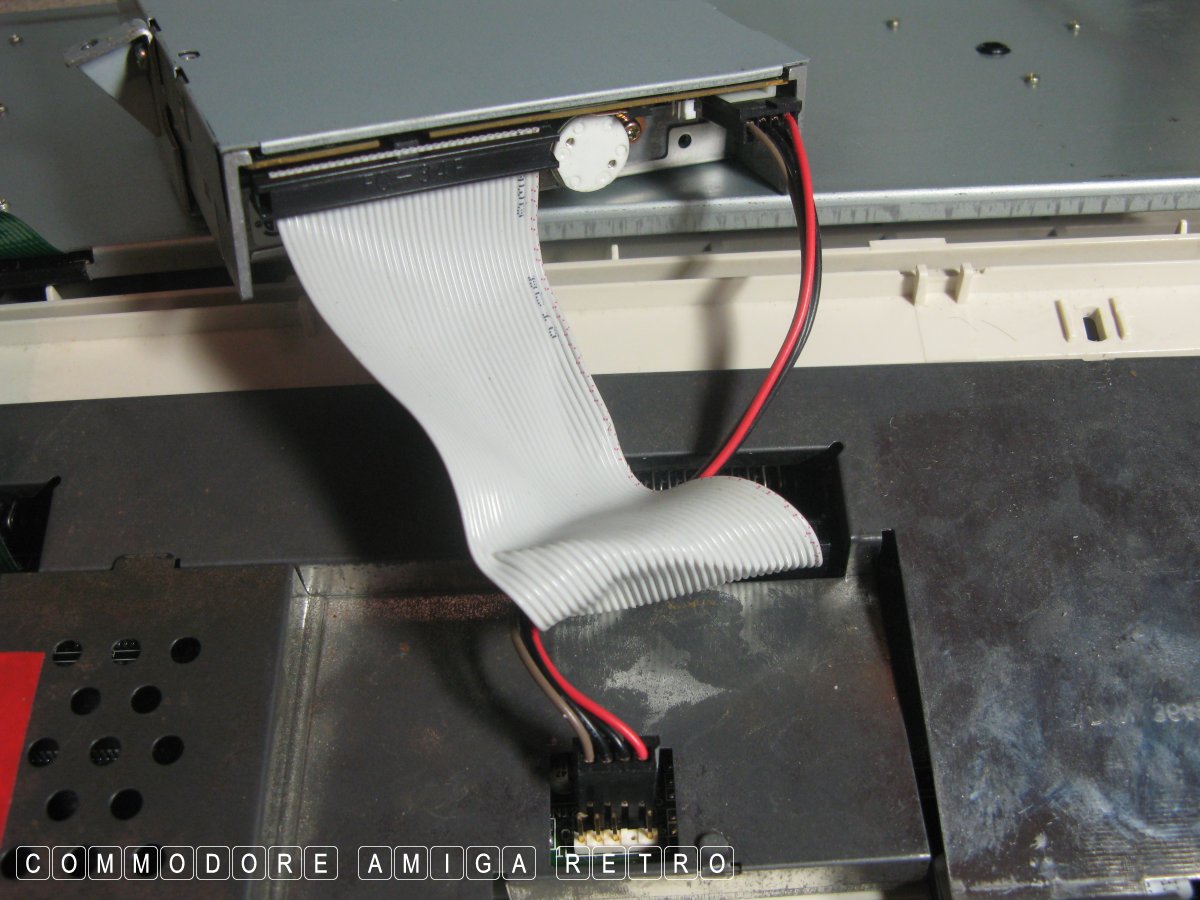
Then remove the floppy ribbon making a
This is the small ribbon to the hard drive.
Although I show the ribbon removed from
TIP: You can fully fold the hard drive over
One screw left to the floppy drive and it
Sometimes easier to leave the connectors
This technique of folding over the floppy
Keep all your floppy bits together and make
The shielding is littered with metal tangs.
TIP: Fold down all the tangs with the exception
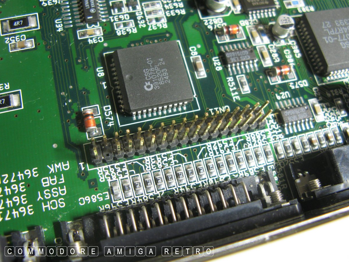
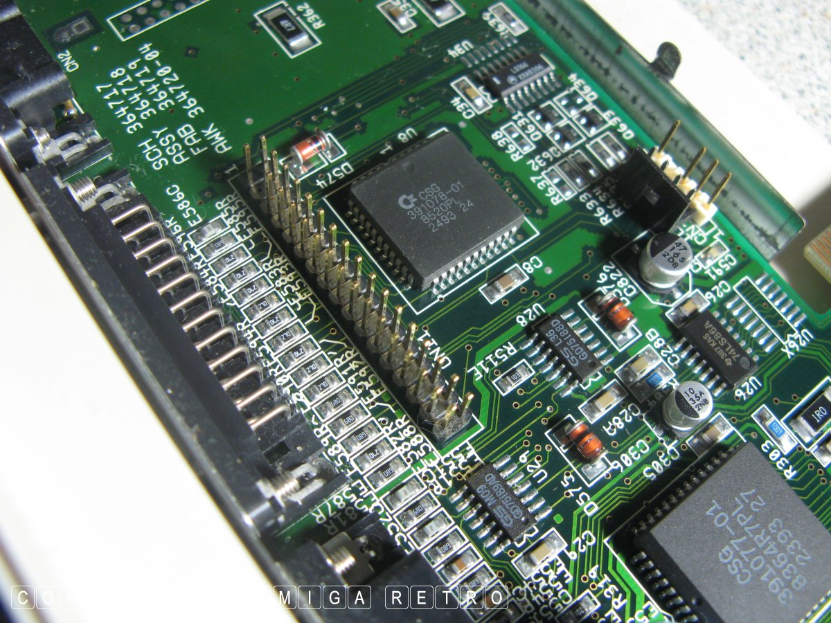
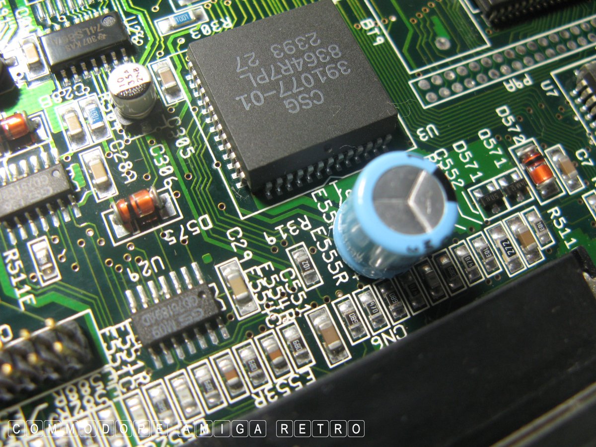
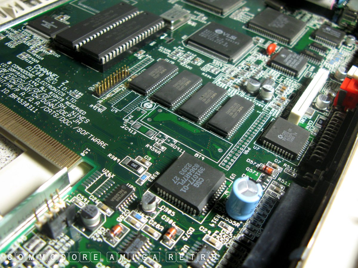
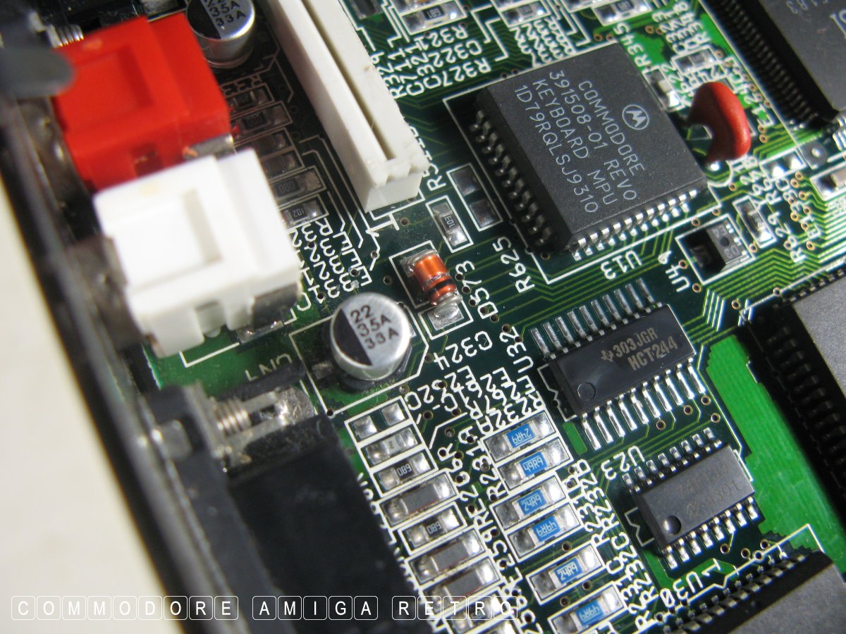
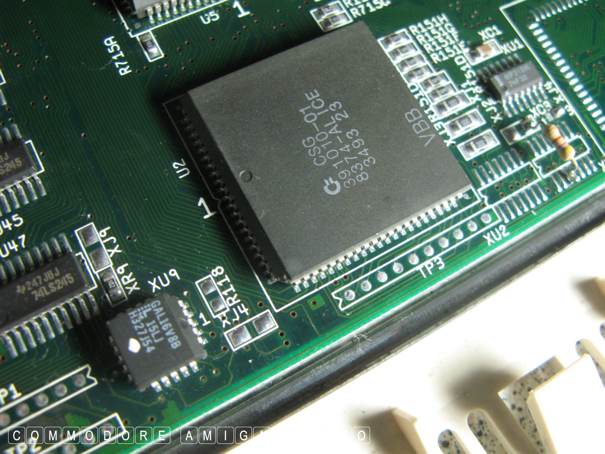
OK Onto the motherboard. I shall be brief.
That's a clockport in the middle with half
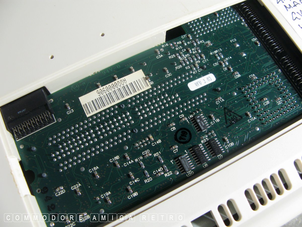
Note the revision of the motherboard. It's not
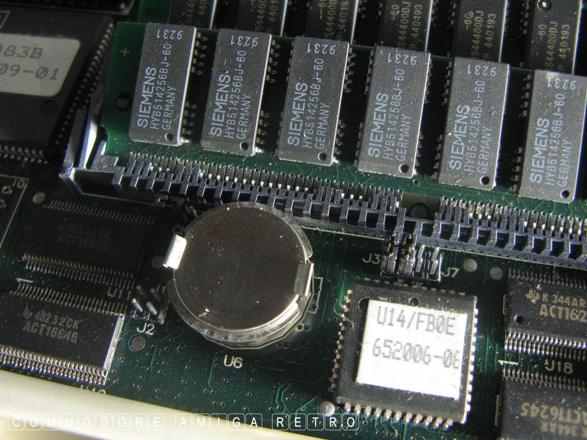
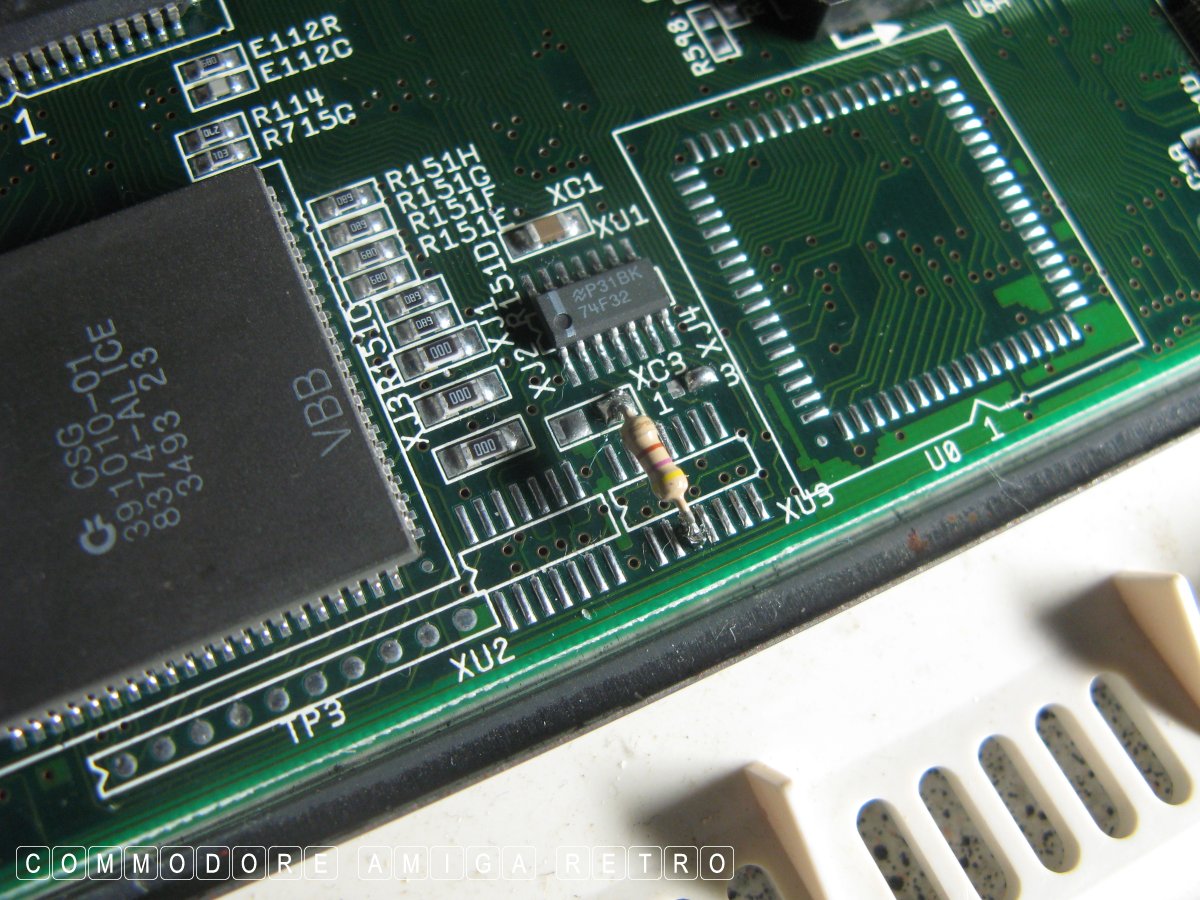
Not sure Quality Control did a good job on
Don't worry there is always a pin missing
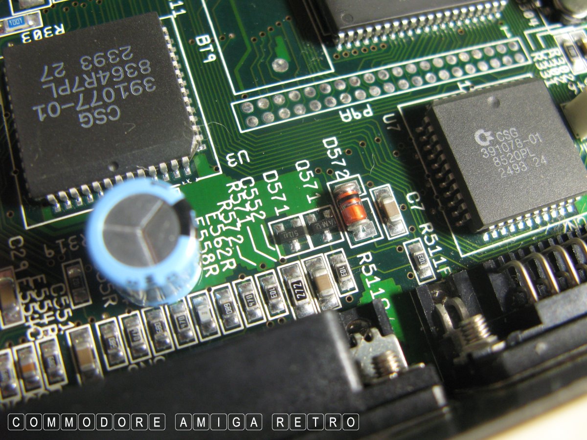
What we are looking for is shiny feet connectors
I saw none of the above so I made no further notes.
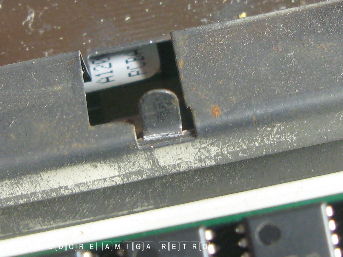
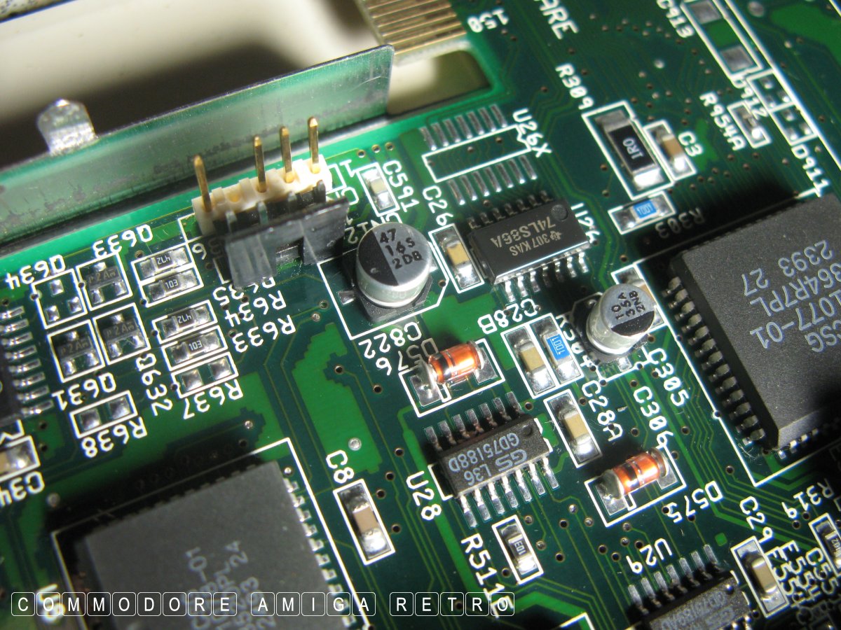
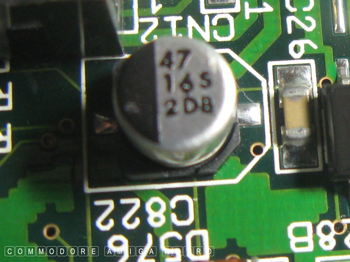
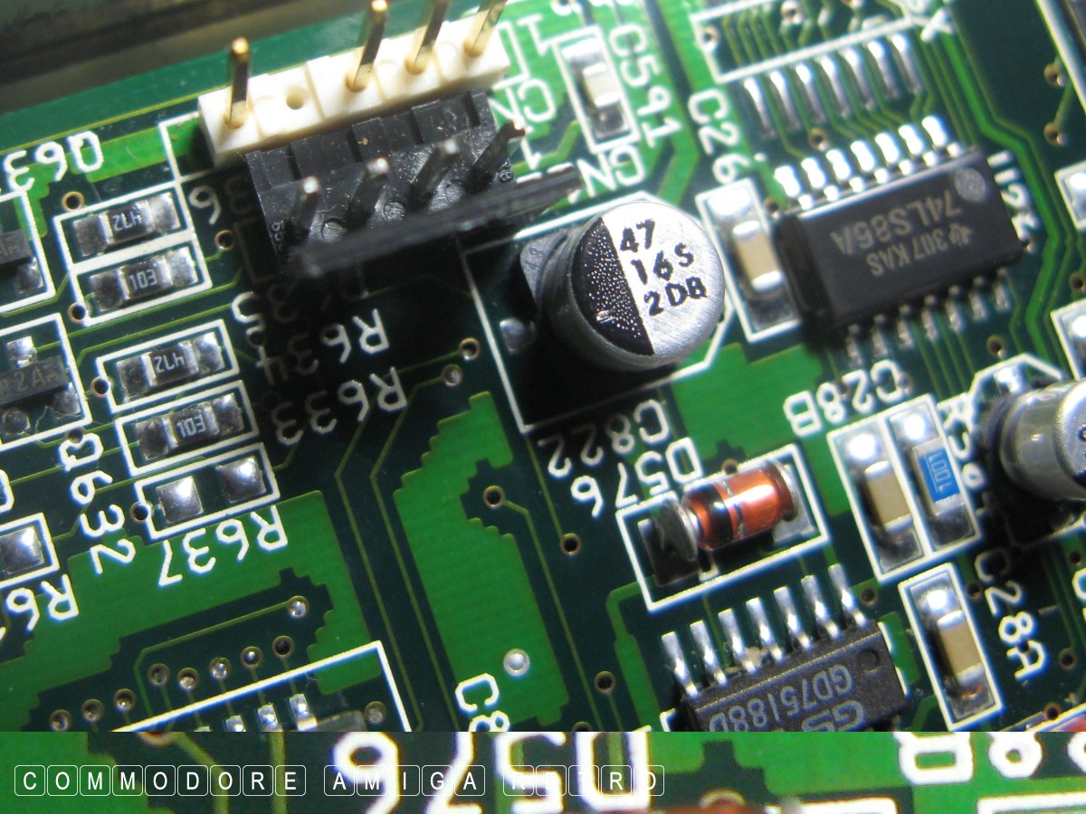
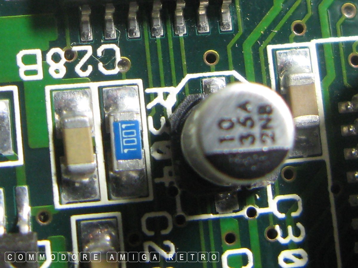
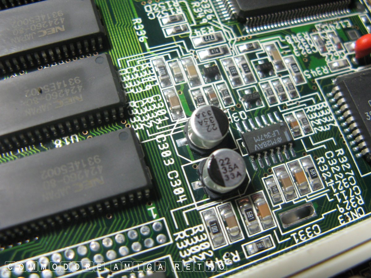
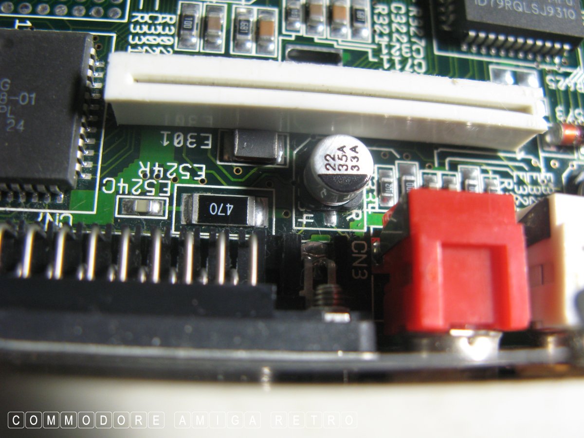
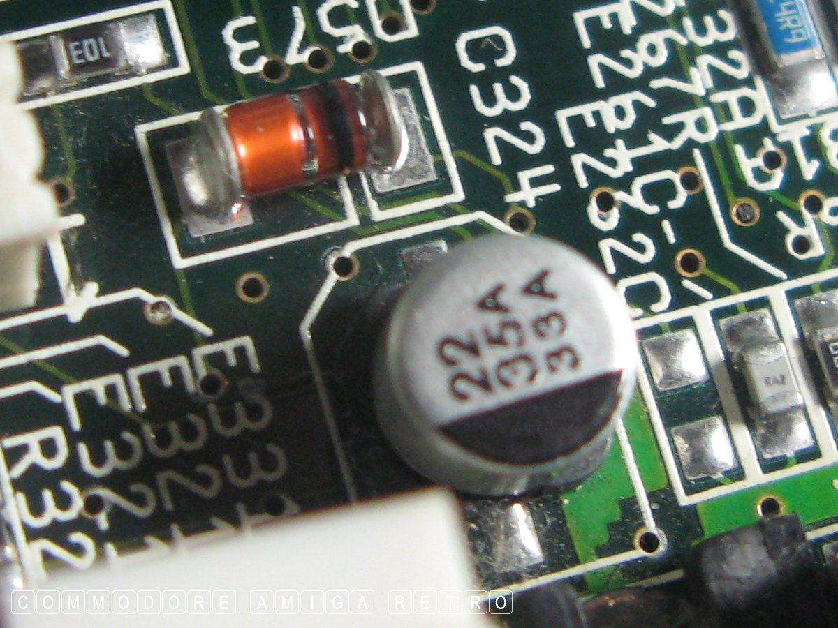
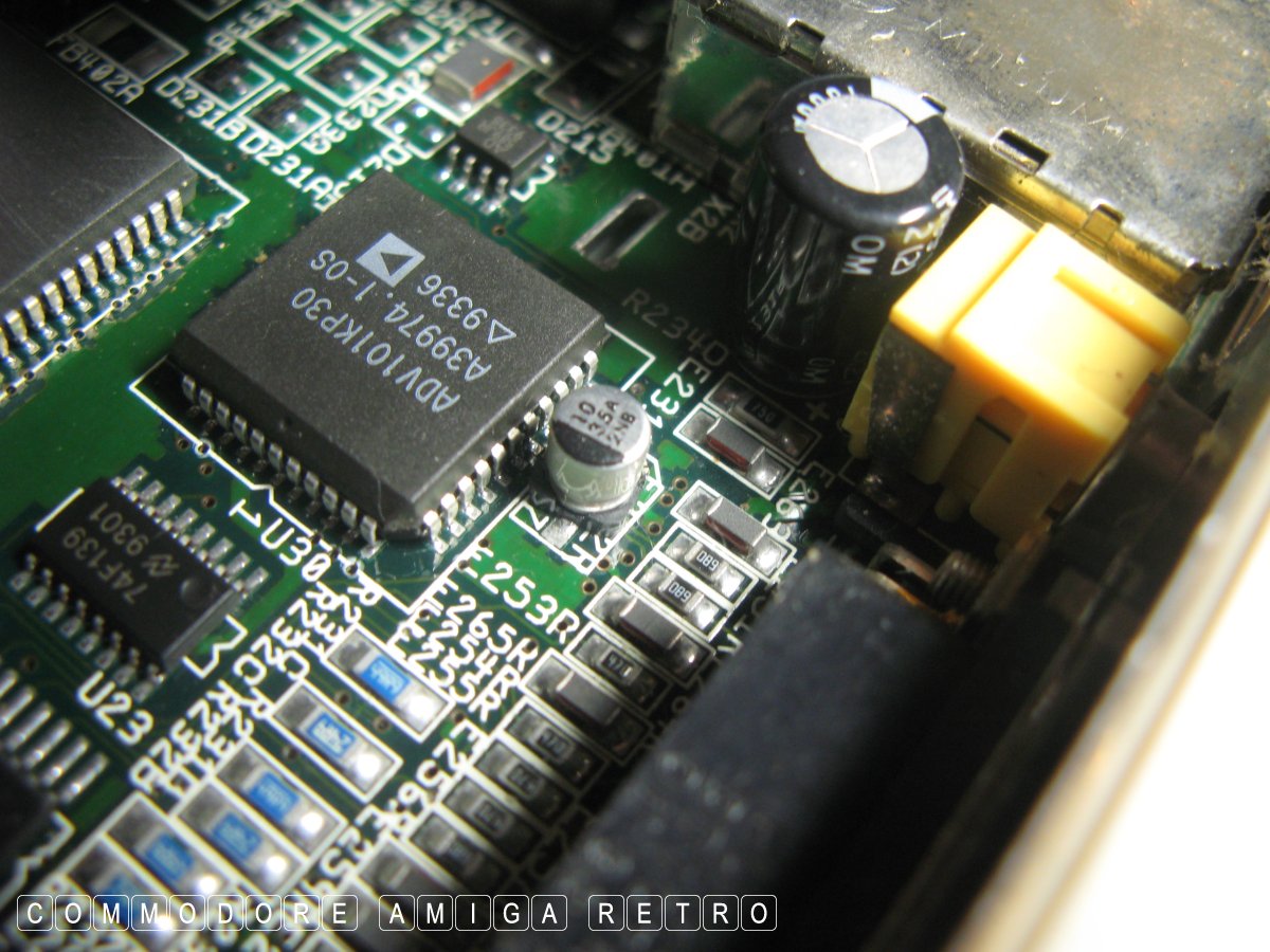
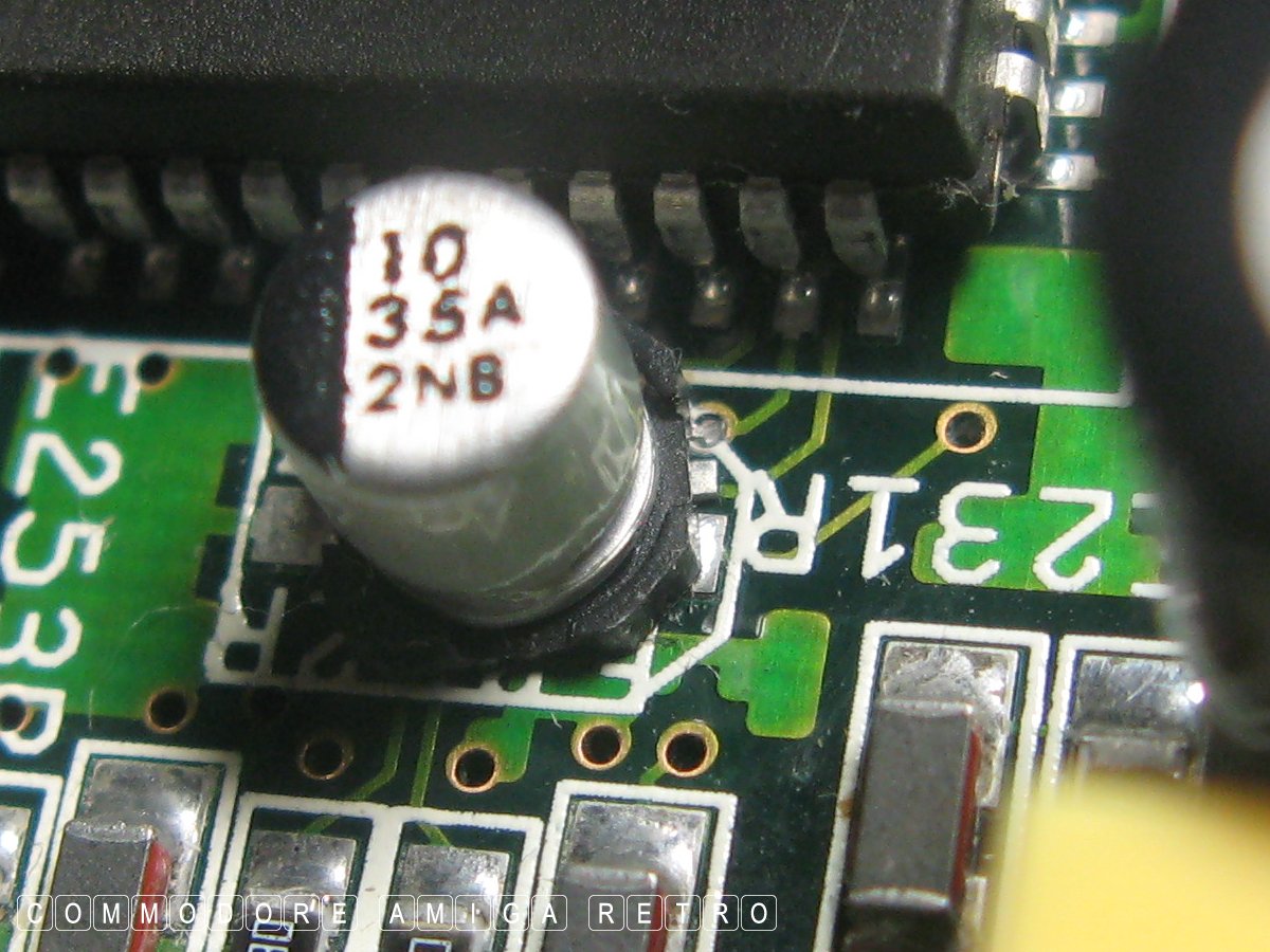
The dodgy crooked capacitor
Different boards have the odd different mod.
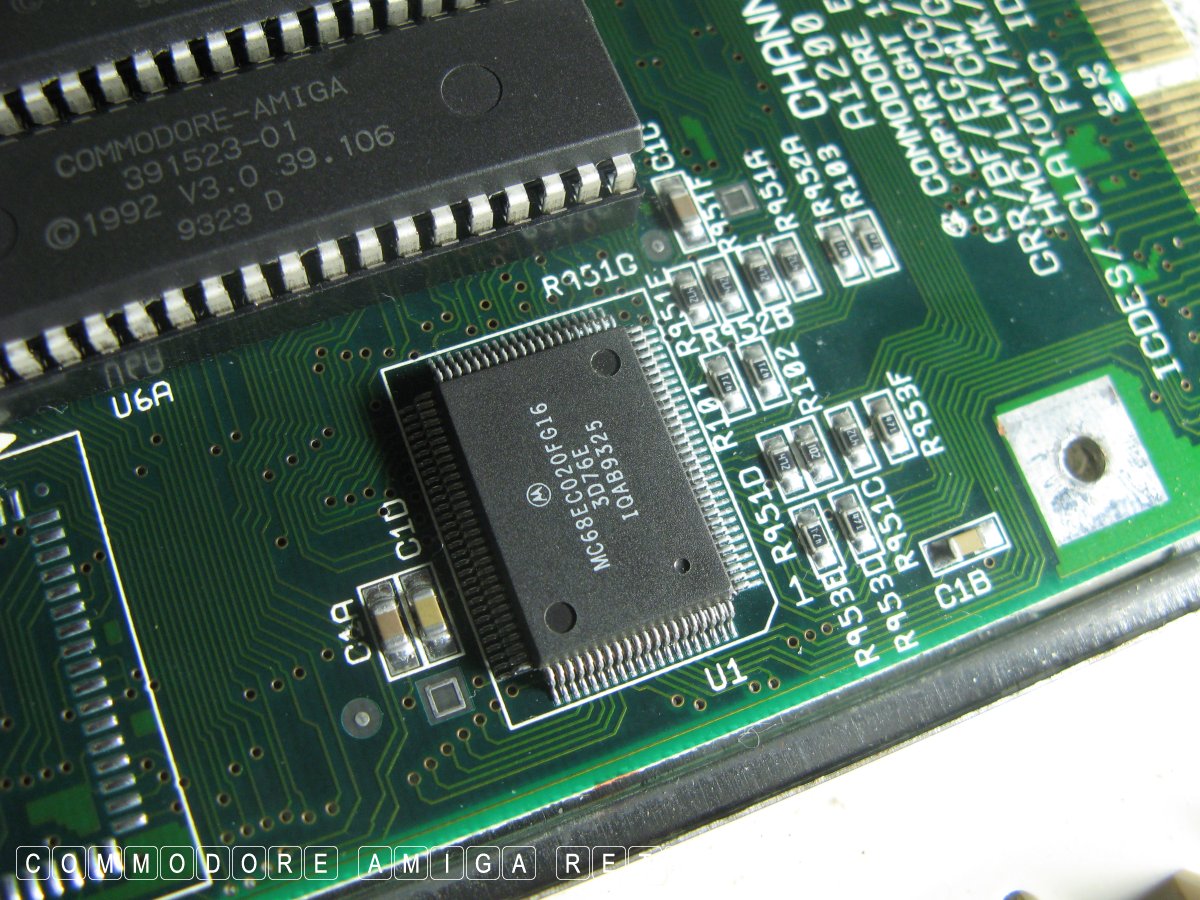
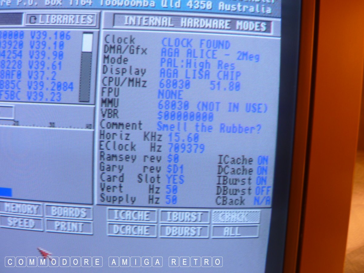
The board is but an 020 processor but the
Talking of which always insert the accelerator
Make a note on the base trapdoor of anything you do.
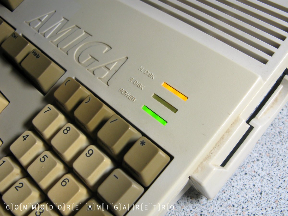
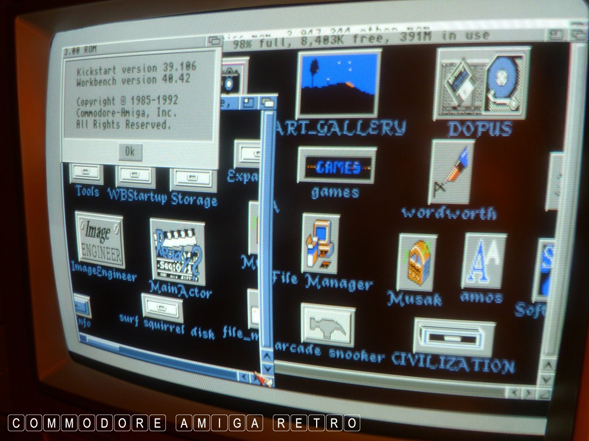
Watch the magic as she boots up. Do a soft
Sorry for the shaky hands, but you get the idea.
Yummy !!
GVP with the SCSI.
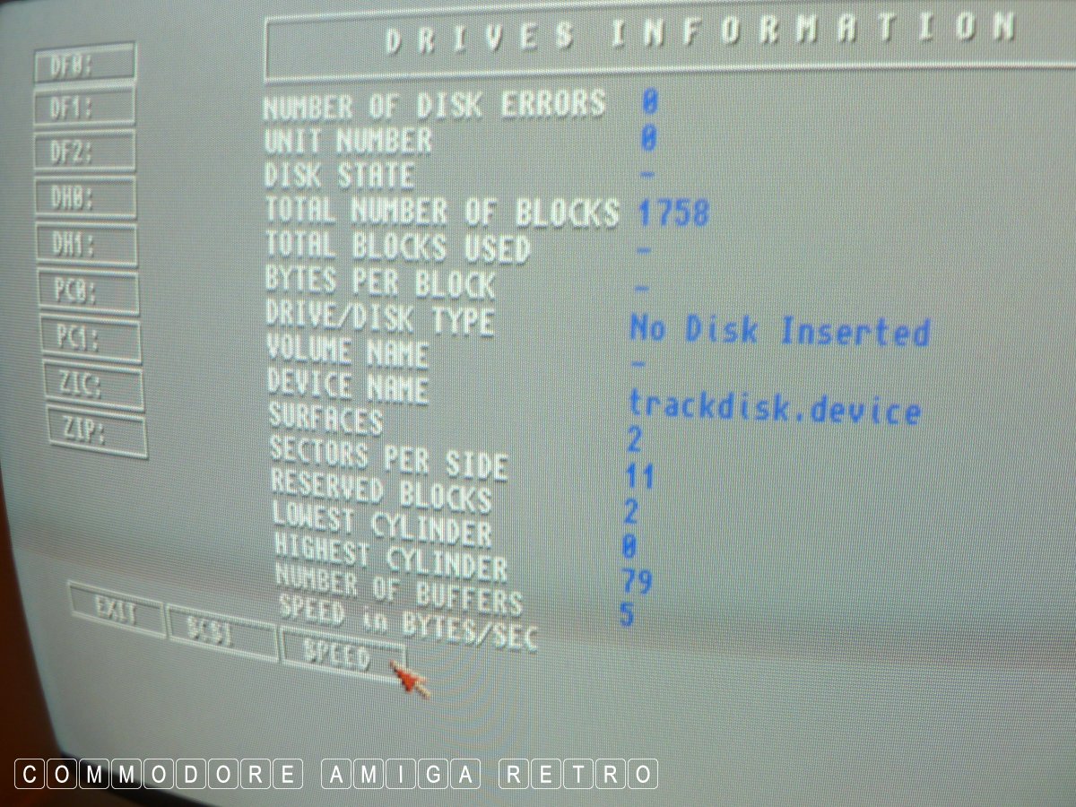
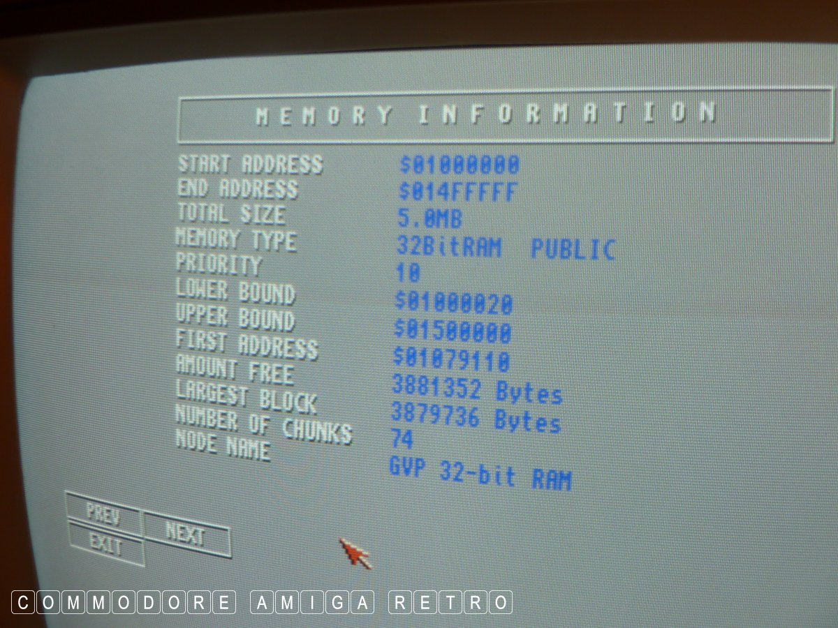
Checking additional memory.
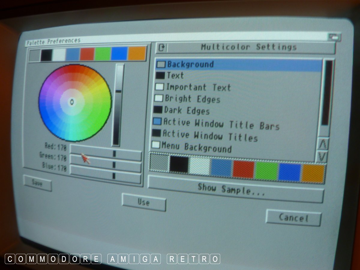
And the colours are all as they should be and
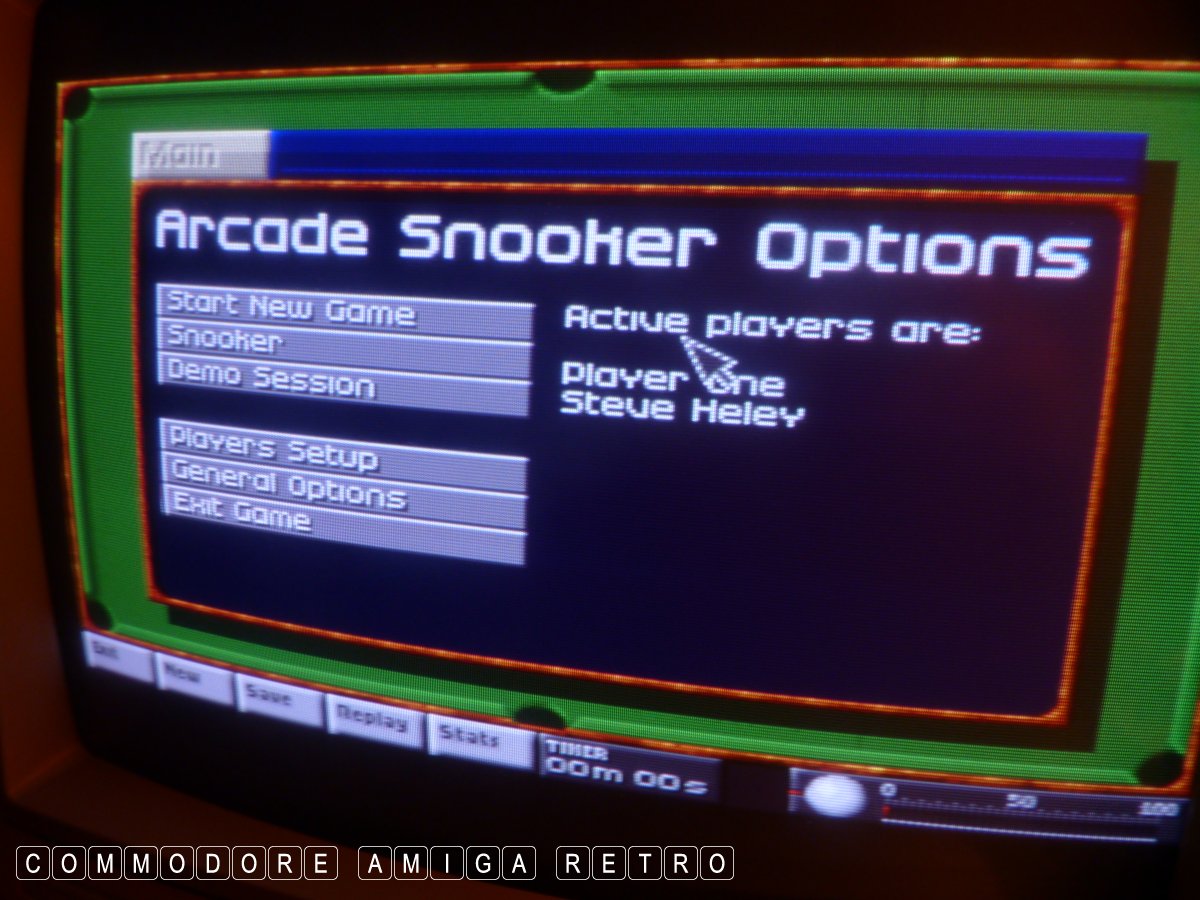
And with all that done I can play snooker.
Now go away...

ScuzzBlog: Diaries February 2025
Entry 13th February 2025: Post 1: Amiga 1200 - Strip down and motherboard check.
Amiga 1200 - Strip down and motherboard check.
I have finally determined that the dodgy capacitor at the funny
angle has always been that way. Somehow the A1200 was manufactured
with a capacitor out of line with the pads, but somehow managed to
get through quality control. The capacitor shows no evidence of
leakage and is secured solid in place, and is working.

What started as a basic record of just what was inside this A1200
was extended to cover all components. I decided to use it as a
mini guide on how to dismantle the A1200.

This computer gets hammered. She sits in the workshop and I use
the 1200 when on the bench to create and check disks as I am working
on computers. She is my main gaming machine and very often runs in
simulation mode when I play SWOS and Settlers, SIMCITY etc plus I
do enjoy my snooker. She has sat in this location for the last ten
years and I have to say I have no knowledge of ever before taking
the shielding off and inspecting the motherboard.

Whilst the board was a little dusty etc she was in first rate state.
There was no evidence of capacitor leakage and all feet, with the
exception of the dodgy angle one was 'shiny' and no dulling. There
was no obvious track discolouration or staining of any kind. She
also runs perfectly and no tint on the screen from the video out.

You will have to scuse some of the hand held images. I was starting
to fall over having spent three days on this project. And yes it
was a joyous 9 degrees C on the bench.

Anyhoo I have moved the computer up here so I can clean up the hd.
She is set up for the Surf Squrrel so I can ZIP her contents here
and transfer to the emulator before formatting the drive.

I only started this process cus I couldn't recall ever taking any
pictures of her contents. She has one of a number of GVP JAWS II
accelerators I have. And amazingly the clock is the correct time.

Seriously.. Happy days !!

PS I'm not proud to admit but with 125 Amigas not own of them
has been recapped. That one I take to the grave. Sorry.
Amiga 1200 - Strip down and motherboard check.
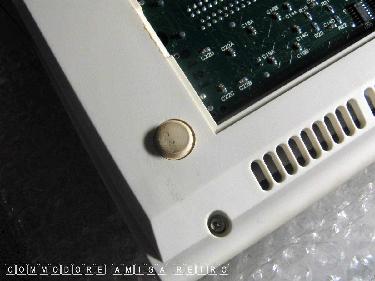
they have gone all sticky. Happens.
than those at the bottom. Be mindful of the
length cus if you screw these into the bottom
edge they are likely to go straight through
the Amiga face-work. So beware. The screws can
also be the 'star' type so use correct screwdriver.
tother side.
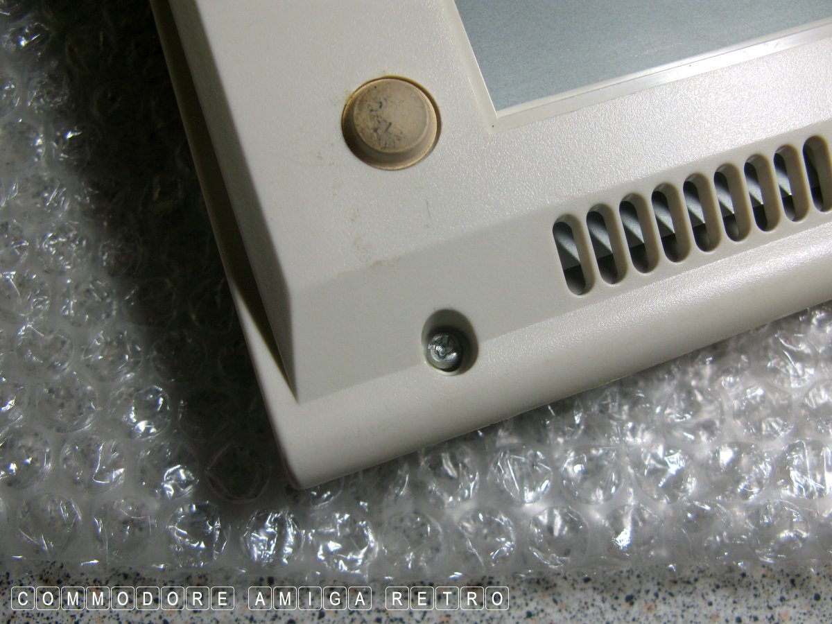
The middle one can be hidden by the warranty
sticker. If the sticker is unbroken then means
the Amiga 1200 has never been opened before.
the finer thread for screwing into metal. Don't
get screws mixed up.
but in this instance we need to remove it. Care
when opening the case as drive may flop down.
and may either be screwed from inside the case or
from the outer bottom. Either will do.
case off the bottom being careful not to break
the little clips that hold it down.
you should be careful not to pull off.
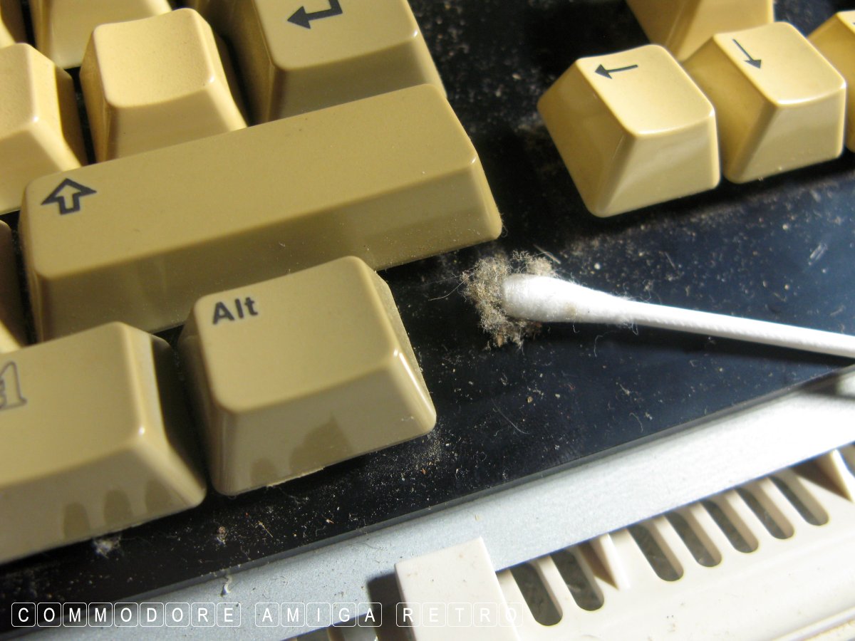
under the keys.
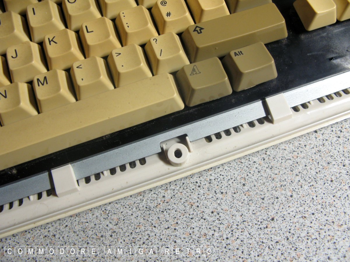
the keyboard. If you lift the keyboard and use
a heavy tall object as a prop, like a large
carton of orange juice, you can stand the top
case and keyboard vertical. If you lay flat
you are likely to strain the ribbon cable.
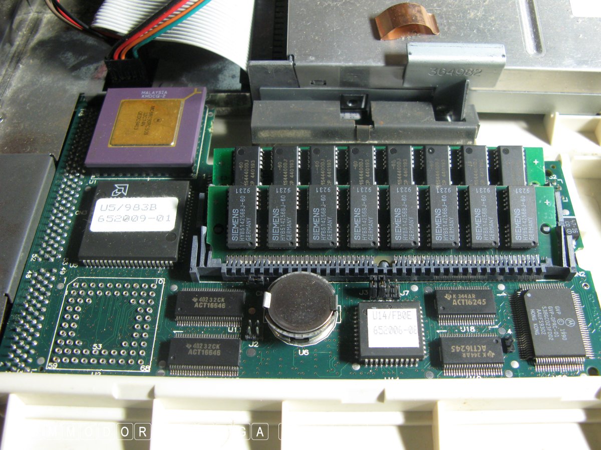
lift out from above as you are likely to bend
the edge connector.
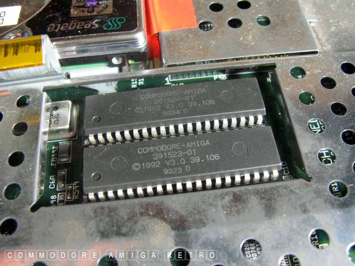
the machine uses. In this instance it's the 3.0 ROM.
ROM also has to go in the set arrangement. They
are not the same. So check the numbers and make
a note of the order. I will not be taking the
ROM out of the motherboard.
this is the first by the trapdoor.
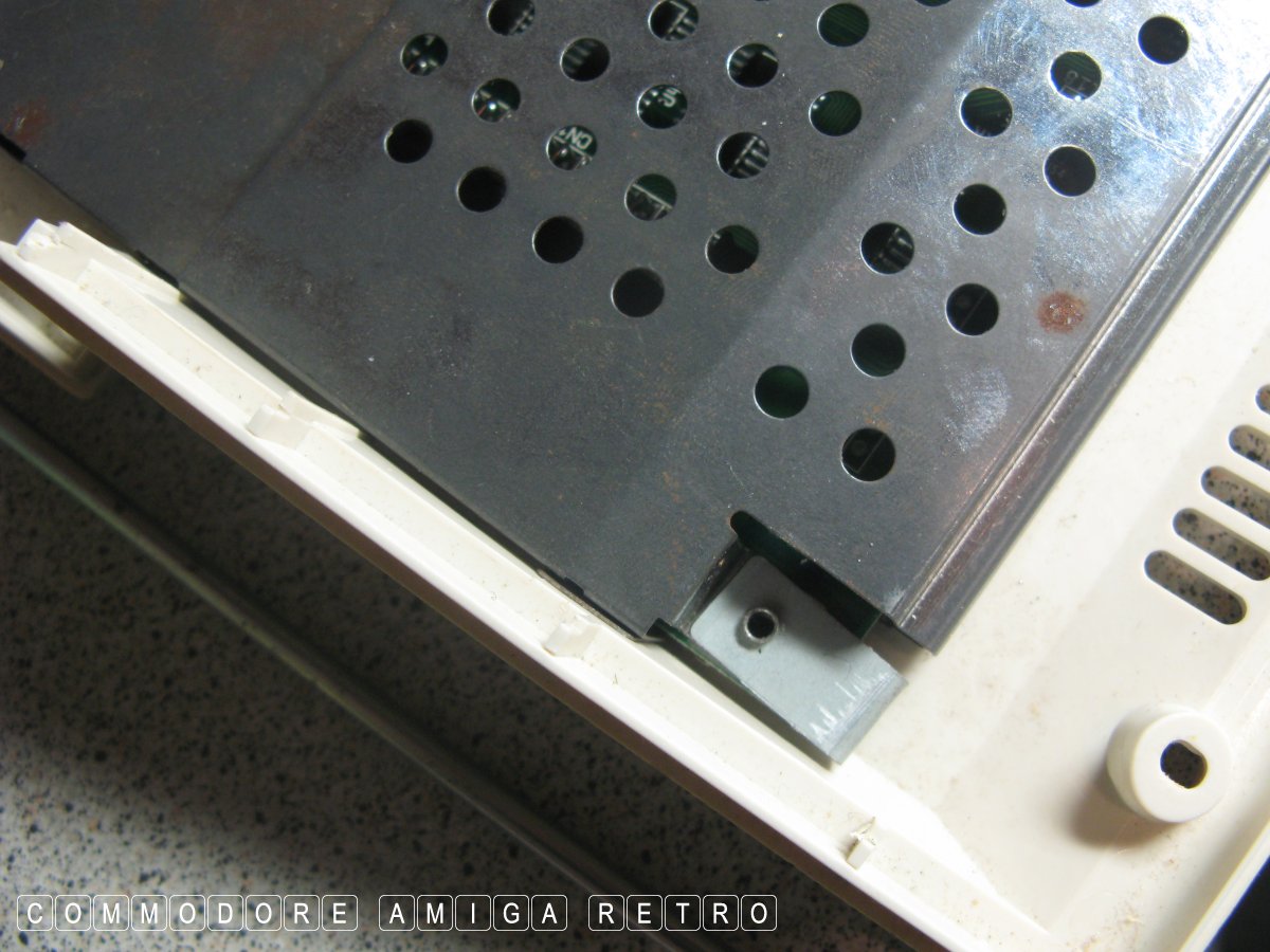
below externally.
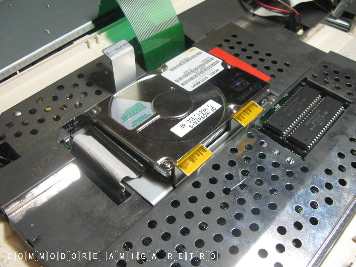
style hard drive which sits in a cradle. Note
the way round the cradle goes.
original team of drives.
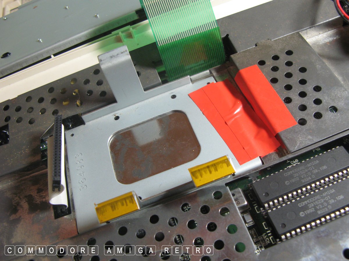
with some tape. The drive should be screwed
down but I never bother.
for the power to the LED lights and floppy drive.
and remembering which way round they went.
TIP The floppy is the one at the rear and
the LED has one pin missing. It is blanked
out on the connector.
a small screw driver and ease off the plastic
white clip. Then slide the clip up the ribbon
and leave it there so you remember which way
round it was fitted.
note of the way round. There is a slot
in the case that corresponds with the same
in the connector off the ribbon.
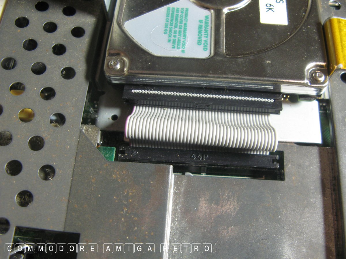
Note the spare pins to the right hand edge.
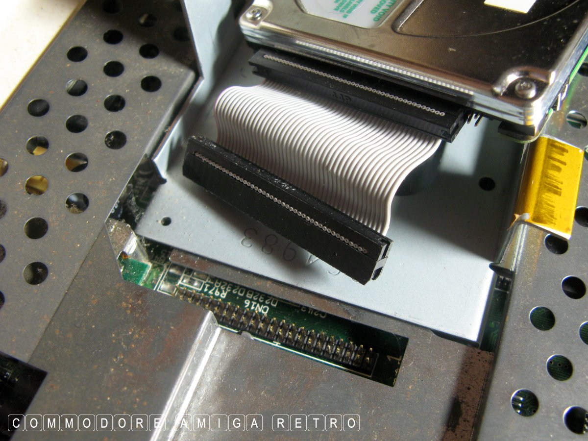
the motherboard its actually better to leave
the ribbon connected to the motherboard.
like opening a page on a book. Its easier to
connect the ribbon to the drive.
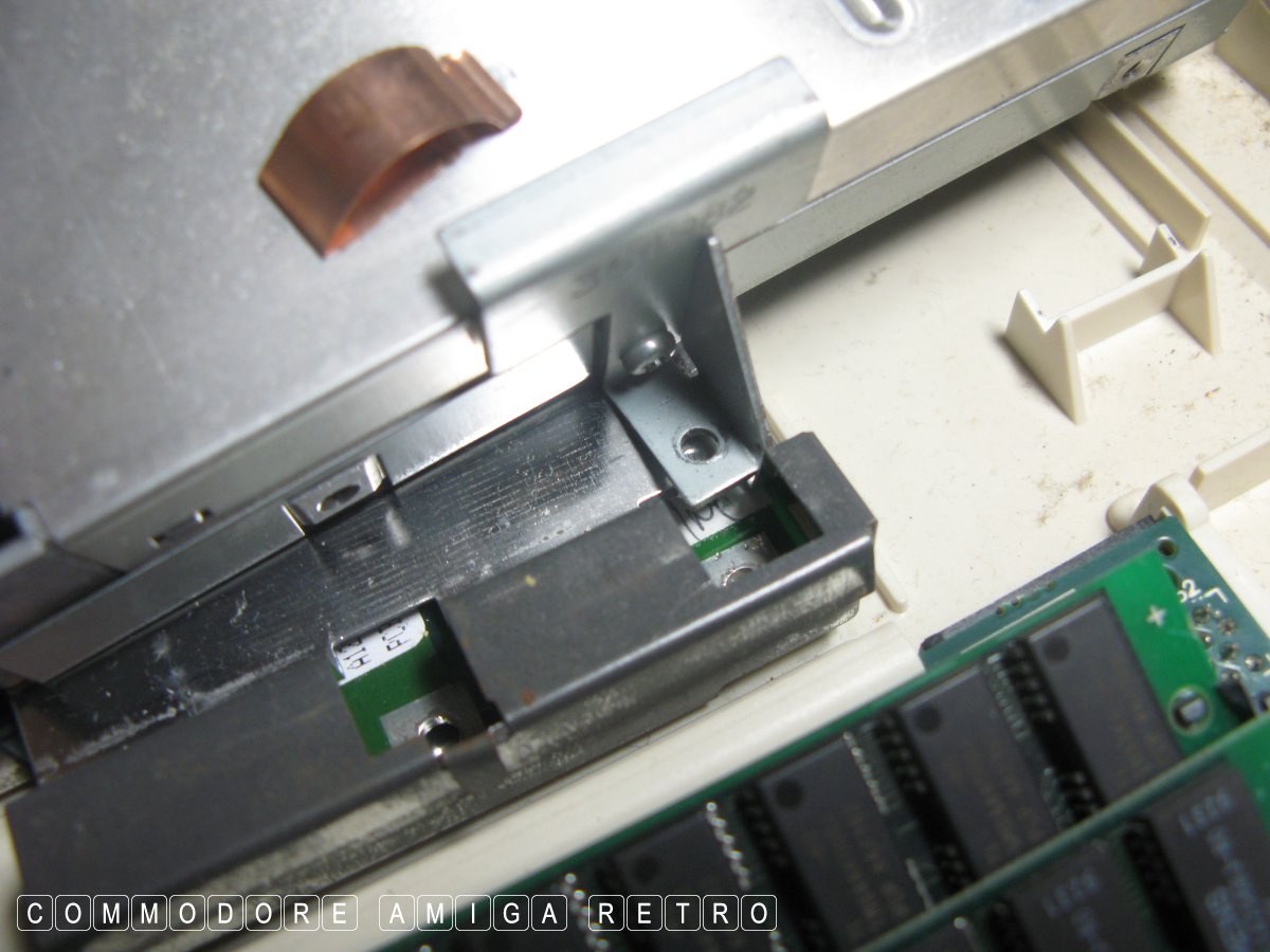
should be a long fine thread one.
on the floppy till you remove that last
screw so you can get a better grip on the
ribbon ends. Try to clasp the black connector
and avoid pulling with the ribbon.
and hard drive is useful when you want to
them in place when you work on the machine.
In this instance I removed both.
a note of the manufacturer. Avoid messing with
the drive.
these you have to fold up to remove.
of the couple by the floppy after removing the
shielding so you don't have to go through this
annoying process again. Just leave the tangs
folded down under the shielding.
The motherboard is the green thing and the
black things are chips. Its complicated.
the pins missing. On purpose.
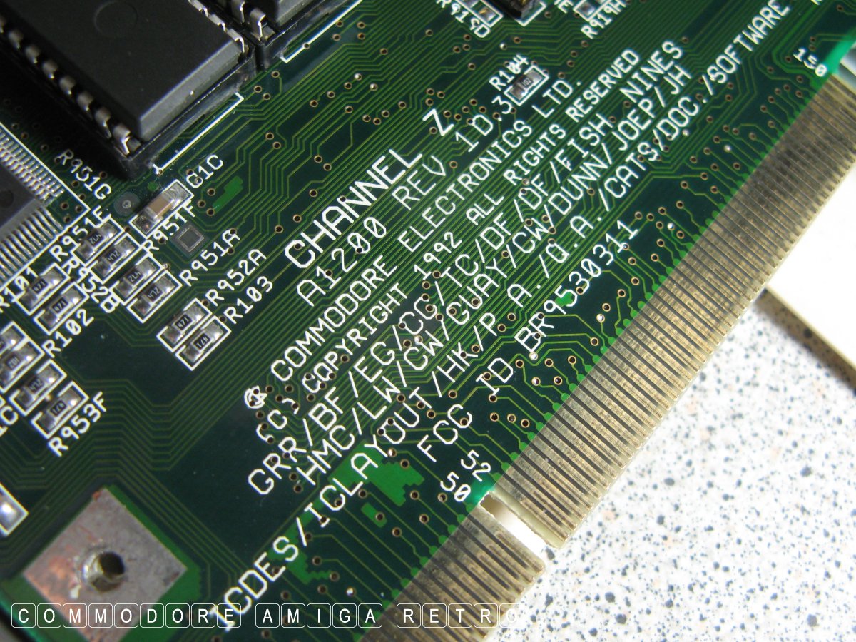
an '0' its a 'D'.
this particular motherboard.
from the floppy connector.
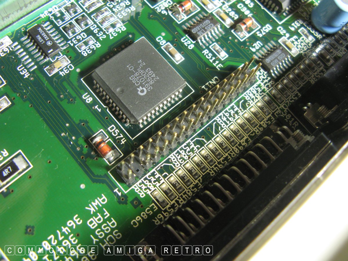
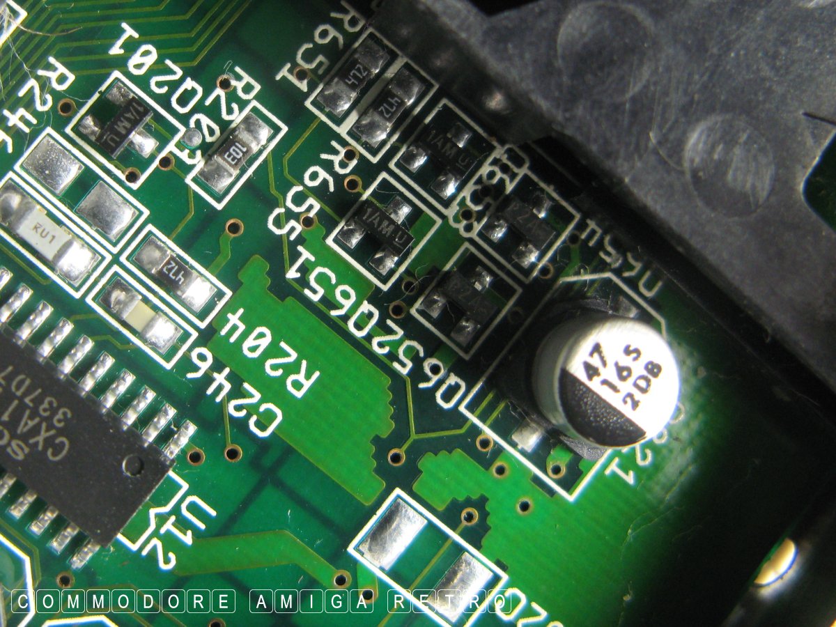
no dusting of solder ie dull grey. No obvious
splitting or bulging of capacitors, no leakage
around the base, no discolouration of the the mobo
or tracks, and no dulling of adjacent solder joint
to components and or damage to those components.
regarding capacitors. Shiny feet is good YAY !

GVP JAWS II is an 030.
in from below as intended. When hooked in
simply lift board very gently onto the edge
connector lining up the little locating slot
and push the card firmly in place.
reset from the motherboard to make sure
the keyboard is working. Also listen for
the floppy to kick in and tick away.
no nasty tint failure as you get with a failed DAC.
If you can only see this CONTENT window
then click the image above for the full site
Last updated 13th February 2025
Chandraise Kingdom
![]()
Keep the Faith
scuzzscink 2025